hi i bought a rostra cruise control and need a micro switch for the clutch and brake to turn off the cruise when they are depressed any suggestions ?
Replies sorted oldest to newest
Allied Electronics via the web/net.... Just about every type Micro switch made. Happy hunting.
There are brake light switches that are easy to mount to a fabbed bracket too. Any FLAPs would have a selection of the, for under $8 ea.
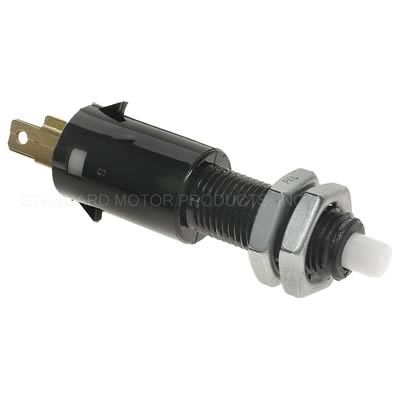
Ray, you can use the brake switch that is screwed into the master cylinder. You'll have to use a relay if you have LED taillights. For the clutch, I'd suggest back at the clutch throwout lever. That's what I'll be doing.
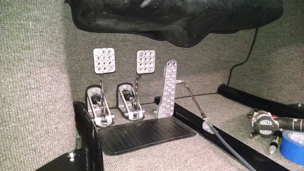
Micro-switches would be extremely difficult to hide in the interior pedal area with our bottom-hinged pedals. Most cars don't have this problem, but we do with our little fakers.
Thanks for the help.
FYI. IM have a panel that hides the type1 pedal cluster and that is why the location on the cluster could work.
FYI also, in the original rostra that I installed in the 80’s it had a ball chain like a pull light chain and the micro switch went on the brake and you tied a wheel direction change unit on the fire wall then tied it to the clutch
whenever any pedal moved the switch went to ground
it was simple and it worked but I did havr to adjust it once when it got loose.
Trying to do something that will be easily done so your idea of the switch on the clutch arm might be better if I also use the brake light switch.
Attachments
I use one of these for my brake switch:
1950 Chevrolet Pickup Brake Light Switch
Been on there for years, now. I just bent the last 1/2" of the arm at 90º to ride against the brake pedal. the switch housing is screwed to the floor. Your IM floor board would cover it all up. Step on the pedal, the lights come on. You could use two - one for brake and clutch. I found they last years longer than the hydraulic switches on the M/C.
Here is another link the fellow adds two types of switch one is a spring loaded with a chain... and another to the back of the pedal cluster.. two switches


Attachments
Ray, please continue to describe the installation. I am curious about what happens in the engine compartment.
Here is a spring type switch that could be attached to the firewall if you have room and then it could release as soon as you press on a pedal ... you might be able to have one switch do both. switch link

Attachments
Since I have a Subie with a drive by wire pedal ... read this as rheostat, I do not need a servo to pull the throttle but you could get that unit if you need it.
www.thecruisecontrolstore.com Mike in tech support can give you what you need.
HEre is another switch ... pretty cool too. cool switch... might be able to attach it easily to pedals. but it is a normally OFF switch and you pull to activate. I think the other above is a normally closed ie pulled is off and released it springs into action full pun intended.

Attachments
Michael McKelvey posted:Ray, please continue to describe the installation. I am curious about what happens in the engine compartment.
FYI, with drive by wire nothing in the engine compartment. if you can get the VSS or a cable speedo hookup then you will have a different set up. Finally if you don't you install 2 magnets, epoxied and tie wrapped around the inner axel and install a sensor pick up 1/2 inch from these magnets that are rotating to generate a speed pulse. Just saying
But that's on an IRS car. Can't do it on a swingaxle car. I'll be using a VSS that screws into the speedo cable, since I'm not using that(GPS speedometer).
Michael, I'll chronicle my install, it may be more helpful to you. I need the electric throttle servo, brake and clutch switches, tach output, and the above-mentioned speed sensor. And I also have an aircooled motor........
Yes the aircooled motor that is the big difference... just kidding.
Danny outside of the VSS, you will need the servo to pull the throttle, so you will have to install it in the engine bay. Everything else is the same, micro switches for clutch pedal and main switch. Here is a pict of their universal controller they supply in my kit that you place somewhere on the dash or under. Your other options is you can make this up with 3 switches. On/Off switch and two temporary or momentary switches.
I would be interested in knowing what kind of micro switch you are planning to install.

Attachments
Here is a guy who fabricated a micro switch for the brake light but I believe it could be made to work for the clutch as well... Pedal Micro Switch This allows the pedal to function as normal and when your pedal moves the unit deactivates the cruise.
It attaches to the back of the gas pedal. It might be a good idea to try to hook up a longer bracket to allow both the clutch and the brake to operate the same.
What do you think Danny... it keeps it low in front and with my panel those would be hidden from view.


Attachments
Ray, agreed, it is a similar install, just more for us non-drive-by-wire folks. It's a bit more involved to get to the same place.
Mine has the same control panel, haven't decided placement or replacement with switches. If I do some small switches, they'll be small toggles.
The servo unit is going in the left well just in front of the LR tire on the firewall. This area is protected from any splash from the wheels. This way all wiring will be on the left of the car. Make sure to keep your VSS wiring away from the main harness to lessen noise pickup.
That brake pedal microswitch looks perfect for you.
@DannyP I just had a thought that the bracket previously mentioned above will not work for the clutch but only for the brake as it will be too long to hold properly and may require continual adjustment.
If we could attach a bracket on the two metal tabs of the gas pedal and we could put the micro switch touching the clutch hook, and then whenever the clutch is depressed, the microswitch would not have contact.
Now there are two ports on the Rostra to address either a switch that is open or closed. Thoughts?
Ray

Attachments
Those are pretty cool pedals but totally exposed .
i found some pretty interesting micro switches at a local electronic supply store which could be used on the clutch tranny arm or any pedal that moves so long as you can hide them
Yeah, you're on your own. The picture above is the footwell of my car. I'll be rigging up a pressure switch on my hydraulic clutch as well as splicing in to the pressure switch wires on the brake pedal.
IaM-Ray posted:Here is a spring type switch that could be attached to the firewall if you have room and then it could release as soon as you press on a pedal ... you might be able to have one switch do both. switch link
Update, Ordered and this part is on it's way to be installed on the clutch lever of the tranny to be a disconnect for the Rostra ECU.
Started .... I was able to install the two magnets 180degrees apart on the inner axle flange and epoxied them and tied them with a tie wrap... I previously found two M8 holes on the Subie Tranny to fit a bracket to hold the sensor.
Do I envy those who can goto ACE and get hardware here we cannot get M8 SS... without a lot of effort.
Now that I am planning to go to Tour de Smo', I have started thinking about cruise control.
Dakota Digital sells a GPS unit that can provide the speed information to the cruise control. That seems easier than using the speedometer cable or something stuck to a rear IRS axle.
Installations I saw on theSamba showed passing a new cable through the fan housing. I have CSP throttle linkage and wonder about running the cable on the face of the fan shroud and pulling sideways on the CSP bellcrank. Years ago Oldyeller suggested pulling on the cable at the gas pedal but Gordon didn't like that idea. It sounded easier to implement to me and would keep the engine compartment cleaner looking.
Attachments
I had that CSP carb linkage. Nicely made.
The magnets are a piece of cake to install FYI
The wireless switch here is interesting:
http://www.rostra.com/aftermar...y-rostra.php#2501483
One of the systems I looked at seemed to say a clutch switch wasn't needed because of a tach connection.
@IaM-Ray when convenient, can you post a picture of your magnet installation?
Can the clutch switch be installed at the lever on the transmission?
Can the brake light sender be utilized instead of a switch on the pedal?
Yes to both questions .. in the end the clutch arm on the tranny I fitted a micro switch it was easier...
brake light switch can be used
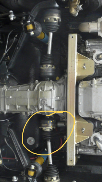 You simply take a wire measure the circumference with it mark the half way spot and mark the cv joint at 180degrees apart. Then clean weel epoxy and use tie wrap to hold till dry closest to tranny
you need to bent the bracket and install the sensor 3/4 inch away
run wires to cPu
cant send real pixt yet i sent a sketch ... yellow area
Attachments
@IaM-Ray thanks for continuing the conversation.
Instead of using the brake light thing on the master cylinder, could I tap into a wire going to the brake lights in the rear?
If I use the wireless switch, it would be nice to keep all of the wiring in the rear of the car.
Rostra module usually want the brake circuit on the top end and not the bottom end feed for the tail lights
maybe a relay could help to meet whT they need you’ll have to check with the tech guy to confirm I believe the circuit needs to rest a ground
I talked to someone at the Cruise Control Store and he said I could tie into the brake light at the rear. If I use the wireless switch and clutch switch at the transmission, I won't have to run any wires from the front to the back. The guy talked like the clutch switch is optional.
Well I tried that and since it was after the Brake Light Switch the circuit does not rest at ground ( the tech says if it finds no ground you get no activitiy at all so their CPU will not work. So I am trying to use a relay and I will try it and report. .. DannyP has the right idea merging into the BLS... I just haven't spent the time to find mine as it is buried. I may still use the microswitcht setup that the fella on samba is selling for $30 because it would easily fit on the pedal cluster. Anyway...
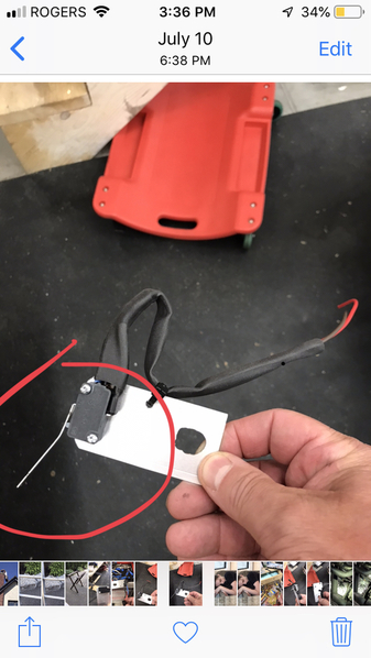
BTW< The micro switch attached to the clutch tranny lever is adjusted so that the switch is pushed in normally, when the clutch is depressed the lever moves away from the switch and makes it goto Ground this forces the Cruise into Nul Mode... coast.
Finally, from the tech at Rostra directly, since the circumference of the drive shaft is 12.5 inches I am presently adding two more magnets to double the pulses. Why? when the system was originally designed most cars had 3 inch diameter drive shaft and thus about 6 inch around which worked well in the past but now with 12 inches the CPU needs to see more pulses. easily done.
BTW, the guy that I used at CCStore was Michael Fox, he helped to clarify the issues I had and the Rostra senior tech in charge of all the tech support is a guy called Thomas.
Michael McKelvey posted:Can the clutch switch be installed at the lever on the transmission?
Can the brake light sender be utilized instead of a switch on the pedal?
Unless you have LED taillights, then you need to isolate the cruise input with a relay.
I'm running a couple small brake lines, a tee, and a separate VW brake pressure switch for the cruise coast switch. I'm doing the same with the clutch, I have a union in my brake line where a tee will be inserted. This completely separates both inputs from the car, and dedicates them to the cruise. Also, the whole unit except the speed sensor and control switch is going in the engine compartment.
I do have LED lights so I would need a relay. I understood the guy at the Cruise Control Store to say that I could connect the relay to the wire going to the brake lights in the back. @DannyP, what are you doing for the speed sensor?
Since I have a GPS speedometer, I'm using a VW cable and Rostra speed sensor designed for Ford/GM transmission. Also a custom made nut/washer to replace the VW nut from the speedo cable.
Clutch micro switch on plate attach to tranny- Pict 2, FULLY DEPRESSED clutch is out.. Clutch in the switch opens and goes to Ground... killing cruise.
Pict one - Shows how to epoxy magnets hold down with tie wrap for 12 hours..
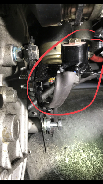
Pict 3 shows bracket (black) which is bent to hold the coil pickup, about 3/4inch away and feed wires to CPU via pulse divider unit.
......This last pick shows how easy to bend the bracket and attach it to the tranny or body and the magnet/coil pickup is lined up with the tie wrap holding the magnets... This is the simplest install and has no drag on the speedo, in my opinion.
Choices is what you have. ![]()


