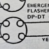
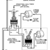
Ok, could someone explain to me or have a good pic/ diagram of what wire goes where? This one is stumping the heck out of me. I look up dp dt and only see 6 prong switches.
Replies sorted oldest to newest
What turn signal switch and hazard switch are you using? Can you show a bigger area of the drawing that you are using? There are several ways to power the flashers. Basically you want to send power from a flasher relay to all four of your parking lights. I think that the switch on the bottom of this drawing shows a similar set-up to your drawing.
Attachments
It's from the fiberfab/ cmc assembly manual (1991)
The diagram helps. Thanks!
So when on, all 4 are connected, and when off, all 4 disconnected, correct?
Kind of.
A DPDT switch usually has 6 terminals. This is unnecessary but workable, you just use 4 terminals. A DPDT switch can be "hot" in either direction. They are often used to reverse connections when on in either direction.
All you really need here is a DPST(double pole, single throw) switch.
@DannyP posted:All you really need here is a DPST(double pole, single throw) switch.
Diagrams like this are frustrating, because they're obtuse, rather than informative. You can't see the arrangement of the switch poles on the bottom (emergency flasher) switch. There is an attempt to show throws with the dotted lines, and a descriptor of the switch, but you've got to know what they're trying to do to know what terminals are doing the switching (I do).
A ladder diagram is just a lot more useful.
True. Once I get a switch, I'd be running a test light on it.
I agree, these diagrams are obtuse. An actual schematic details the electrical paths MUCH better. I like VW's schematics with numbers on each terminal, makes it crystal clear.
Well, except for the German color abbreviations...
I'm redrawing the cmc/ fiberfab vdo schematic in illustrator so I can put better notes in. And have it in color.


