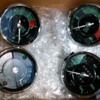
Ive never went more than 600-700 miles before my chinese replica tachometers started bouncing around on me. Hoping to remedy the situation I purchased a set of originals and sent them to North Hollywood Speedsters for 12 volt conversion and restoration. Before I install the new gauges id like to make sure it wasnt my car killing the chinese tachs. I had to sell my first child to afford the conversion/restoration, cant afford to burn up the new tach.

1st question
- does it even make sense that the wiring in my car could be killing the tachometers? Ive gone through 4 of them.

2nd question
- how would I go about verifying everything is as it should be?

sorry to be so vague. I have yet to get a grasp on all things electic.
1956 Thunder Ranch(Speedster)
Original Post

Replies sorted oldest to newest

Ive never went more than 600-700 miles before my chinese replica tachometers started bouncing around on me. Hoping to remedy the situation I purchased a set of originals and sent them to North Hollywood Speedsters for 12 volt conversion and restoration. Before I install the new gauges id like to make sure it wasnt my car killing the chinese tachs. I had to sell my first child to afford the conversion/restoration, cant afford to burn up the new tach.

1st question
- does it even make sense that the wiring in my car could be killing the tachometers? Ive gone through 4 of them.

2nd question
- how would I go about verifying everything is as it should be?

sorry to be so vague. I have yet to get a grasp on all things electic.
If anything is wrong with your ignition, it'll make your tach bounce, kill your CDI box (if you've got one), and generally be a pain in the rear.

I've got Brazilian gauges that I had North Hollywood Speedometer rebuild with the good guts. I had the gauge recalibrated and screened for 8000 RPM. I also have a shift-light with a module from Summit.

I was getting a bunch of bounce even with the new gauge, until I ran down EVERYTHING in my ignition system. I eventually found the source of the problem.

I've got Taylor wires, which require the little ends to be screwed on the NGK plugs (not like the Bosch wires that push on the tiny threads). The ends had loosened up on the plugs, and were making intermittent contact. I found the problem, but not before I spent a boat-load of time and money on the tach, the shift-light module, etc., and had a back-fire in the 1/2 side carb that almost burnt the car to the ground and ruined a 48 DLRA.

If it were me- and I was unsure and didn't want to risk it with the "shards of the true cross" rebuilt tach- I'd wire up a cheap aftermarket tach and leave your tach out of the loop and drive around until it bounced or didn't. Hopefully it does.


If it bounces, remove your CDI box form the circuit (if you have one), and start backwards from the plugs (first plugs, then wires, then cap, the distributor, then coil). I'm sure you've got spare everything, so take it one step at a time. I have a hard time believing you've really had 4 bad ones in a row.

If it doesn't, install your nice new one, and go from there. Having a spare cheapo tach never bankrupted anybody. It's cheaper than killing this one.
I'm wondering the same thing as Wild Bill.

This is the most common problem with Vintage tachs. I also had 4 of them from Vinatge go bad and replaced under warranty.

I finally sent one to North Hollywood for the fix. You just plug it in and your problems are solved. You should check everything out, but it's not likely that it's any other problem other than a cheap Chinees tach.
By the way. Palo Alto gets my business now, they only charged me $165.00 each for the two that I just sent them.
Paul,

The tach has 3 wires related to tach signal. Check each for good connections and signal. You have a 12v switched power, a ground, and the signal from the coil (or electronic box). The power and ground are self explanatory, and the signal wire simply pulses 2x per revolution and can be tested with a 12v test light while turning the motor over. Likewise, all of these connections can be easily made with jumper wires and the tach can be wired up virtually anywhere i.e. wire it with short runs in the engine compartment and see if you get the same "jump" in the needle. In my experience, the tach itself (or 4 of them) is the issue. In fact the supplier now charges almost 3x the money for the tach, however they are sending all of them to North Hollywood to be corrected before selling them.

BTW, I hope you considered that the original gauges are smaller in diameter than the repros... You might be able to cheat the 5mm with a VDO rubber gauge seal, or you can always do a spyder-like gauge insert panel (opposed to reshaping the holes and repainting the dash). If you run into issues just drop me a line. I can scrounge up seals or laser cut you an insert...
Thanks for the great advice Stan and Carey. I do not have a CDI, but will chase all connections down. My coil does move around in its billet mount. Ill make sure to take care of that, cant be great either way.

To those of you that asked "Why"... to me the chinese gauges are a mere shadow of what the originals are. You can see and feel the quality in the German VDO's. They are better gauges period. Details matter to me greatly. Its my job.

Ive also replaced my steering column, that cheepo looking steering hub, turn signals, windshield wipers, all switches knobs and bezels. Still to come... Install original E-brake, Install Eberspacher Heater, install original steering column mount under dash, install original style convertible top frame. After that Ill sell it and buy a tripped down porsche powered spyder. For now, its just fun. Not to mention it keeps me out of the bars, most'ly.

Carey, we actually have a CNC laser cutter in the office to make models. I used it to create a spacer/gasket. Itll have to do until I fill in the dash and recut the wholes. Ill do this prior to reworking the body and repainting the car.

Madness.

Attachments

Images (1)
  • gauges-restored
One thing I came across last night, my turn signals are wired up to separate indicator lights. left signal makes a bulb on the left blink, right makes right bulb blink. easy enough. the new gauge has a single indicator light. any ideas on how to change the wiring so that both left and right signals light up this single bulb?

also, all the chinese gauge lights have a single ground to the case with a hot going into each bulb. the originals require a ground and hot at each bulb. Can i just spline into the existing single groudn wire? what would be the correct way to do this?

thank you
For the single indicator I used diodes.

I put a diode on the wire coming from the left side lights and another from the wire coming from the right lights. Then I ran a single wire from the other ends of the two diodes to the indicator light. Be sure you have the diodes oriented correctly. They are like a one way valve for electricity.

You can use the existing ground. Where it has a push on connector somewhere add one of the things that allow an additional push on connector at that point. You can probably get one at radio shack. Then run your new ground wire to the bulbs from that point.
Gordon beat me to it: your underbelly looks pretty good -- you have colors!! Most are much worse, I'd wager, including mine.

The jumpy tach thing (treated many times in this forum) has almost exclusively been attributed to the circuitry (or lack thereof) of the Chinese fakeroos. Mine was bad from Day Zero. I complained to the builder, and reserached the issue here, and discovered what No. Hollywood Speedo (NHS)can do. I contacted them and arranged to have the innards replaced w/ Gen-U-ine VDO stuff, and was all set to go direct. I told my builder what my plan was, and he said to send the tach to him and he would take it over to NHS and get the work done -- which he did, at no charge to me. The rebuilt tach, w/ the Chinese can and dial that match the other gauge, works like a dream. No other electrical funny business required.
Well.....yes.

I'm not thrilled about the exposed copper in the photo on the right, though.

If you twist those multiple wires together, then solder them, then put an adequate length of shrink tube over them (and actually shrink it) then it'll be a good connection for a long, long time. It will, however, be an un-serviceable connection, meaning that you can't alter it easily (you have to go through hoops to unsolder it, etc.). As a rule, I never crimp or solder more than three wires together - two on one side of the connection, one on the other. This can usually be accomplished by "daisy-chaining" if need be.

Better is to have terminal blocks which you can make multiple connections to and connect things that way with crimp terminations. There are a log of variations out there, many are adaptable to our cars and may or may not be practical in your circumstance. The terminals in Autozone/NAPA/etc are marginal but cheap. Those from AMP or Molex are light-years better but $$$. You should have an adjustable, ratcheting, crimping tool no matter what you're crimping. I've seen a lot of bad connections from over-crimping them (the wires get stressed, weaken and break).

Bundling like-flowing wires with tie-wraps is more than OK, while corrugated, split, wire conduit (found in the "HELP!" rack at Advance/Autozone/Carquest/NAPA) is good, but it can't take a lot of heat (it melts). Nylon spiral wrap is good, too, because you don't have to remove anything to put it on and it takes heat better.

Dr. Clock uses Vintage Wiring harnesses, which, I believe, are not sheathed (in other words, the wires are exposed). He loves them, because they're point-to-point and make nice, neat bundles and are serviceable. The big thing to realize is that you want to establish a route for your wire bundles, stick to that route and don't have a lot of excess length going from A to B. If you do, that extra length will quickly look like a rat's next or basket of worms.

The WORST car I ever worked on was a CMC Speedster that had all black wires going everywhere. Nothing was marked. The guy just bought a huge roll of 18 ga. black wire and ran it as he needed it. Connections were hand twisted and taped.

Scary.....Very scary.
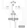
Thanks Gordon. I think Im going to go with Molex Multi Pin connectors. Ill be installing a gas heater under the dash this winter. the quick disconect should really help when figuring out plumbing to the defrost vents. unsnap the connectors and get everythign out of the way. At lunch i drafted up this quick schematic. Never done wiring before... makes sense to me, im sure im using the wrong symbols, etc. need to add wire colors. but its basically showing a 4-pin and a 6-pin connector. rather than splicing all of the wires i think i will just use a jumper from one pin to the other. you can see it in the ground. what i forgot to show was the hot leads using a jumper. will the jumper idea on the car side of the connector work? (car side versus gauge side, input vs. output?) again, dont know the lingo.

While im asking questions... can anyone tell me what the difference between the 'G' and the christmas looking tree symbol is? Im assuming the 'G' grounds to the device sending the signal and the christmas tree is common ground?

Attachments

Images (2)
  • GAUGE-COMBO-SCHEMATIC
  • combo-gauge-back
Jumpers on the connector blocks are OK.

The christmas tree symbol is as Kelly says, the international symbol for "earth" ground or common ground in this case.

What is that gauge?

I would suspect that the "+" goes to a switched 12V source (switched on/off with the key) while the "G" goes to the appropriate sender unit. Most senders are "ground-based", meaning that they provide a "signal reference" relative to ground, rather than referencing the 12V side of the circuit. Makes the world a simpler place.

Post Content
×
×
×
×
Link copied to your clipboard.
×
×