I actually used four for the headlights, one for each filament, left and right, high and low. Mounted in the well next to the battery. High current wires from battery to relays and then from relays to filaments as short as possible. Took the existing wires from the ignition switch to the filaments and just wired them to the control terminals of the relays. I could send a picture. Being all amateur, the result is a little rat-nesty, but it works and works well. The other relays for turn signals, and such are pretty standard, and I did not monkey with those. Allow me to say that I had previously burned up two cheap Chinese light switches. also let me observe that previously, my headlights were not very bright, and I used my external driving lights (which were installed by builder using a relay of their own) quite a bit. Now, the in-car lights are properly bright, and SO much better.
For the battery ground connection on my CMC, I drilled and tapped a hole in the frame where it arches over the tunnel and attached the ground there. I also have the flat ground ribbon from the trans. to the stud on the frame horn and a ground wire from frame to a starter mounting bolt.
Couple shots of my wiring job in the rear.
HUGE thank you to Greg at Vintage Motorcars/Spyder for helping clarify the rear wiring harness.
And a HUGE thank you to the Doc. We had two really good conversations via phone today - he's a wealth of knowledge just like everyone on their forum!
Now, it is time for a Game of Thrones inspired beer in my nerd gamer Hearthstone Inn Keepers beer mug I got at BlizzCon ![]()
Attachments
Emblems. Emblems. Emblems.
That front Porsche emblem was a PITA!
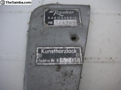
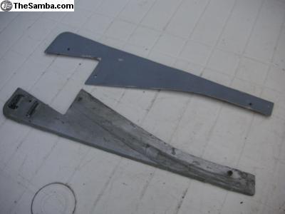
The only emblems left are the VIN and paunt code plate. I'm going to have them engraved with my VIN and paint code before installing.
On a side note - Calling the Doc! I'm going to bug you tomorrow as I try to finish my wiring.
Anybody have a VS with the Bosch ignition added? I'd love a photo of the wiring in the back ![]()
Attachments
Certainly Brian !
WOLFGANG posted:
I've got a good friend who is the Van Gough of welding stopping by tomorrow - I'm looking for a nice battery tray. Maybe he can work some magic? I have the emblems.
Attachments
Greg,.....Where the hell do you come up with all these esoteric photos pertaining to every 'nuts & bolts' subject on this forum?
Everyone needs a hobby!
Carl Berry CT. posted:Greg,.....Where the hell do you come up with all these esoteric photos pertaining to every 'nuts & bolts' subject on this forum?
If only he spent his time wrenching on his speedster garage queen...
MikelB posted:*LongFella posted:Finished the headlights! I decided to use the correct headlight to fender rubber from SMC. Kirk uses a different method and I wasn't liking the look IMO. I also finished all the front-end wiring. It's nicely tucked away (where I could) and wrapped in auto fabric tape. Each light has its own dedicated ground wire too.
Thank you Doc for helping me out with the three headlight wires and how they attach to the wiring harness.
Mandatory pics below. Oh and look at that gas tank! She's a beauty
In pics 3&4 you have your headlight grounds wired to a stud which I assume is the through bolt for the bumper ends. How are you grounded as the bolt is attached to the fiberglass?
Cars looking great, love the color combo.
PS: sorry for the late to party response, just catching up.
I wonder'd the same?
At least this is a short and focused thread.
Circuit analysis is different from earth ground. The bumper bolts are attached to the chassis, which is connected to the negative post on the battery.
Tires by the way are very slightly conductive.
BobG posted:At least this is a short and focused thread.
When is a thread ever short and focused? LOL! ![]()
I'll take a look up front again. I am going off of pics I took while visiting VS and watching the guys do the wiring. I might have missed the bolt they used... could have been the mounting build of the turn signal or they taped into the ground on the headlight wire??
I grounded the rear by daisy chaining the wire across each mounting built on the lights and then to the rear bumper bracket.
I have the main ground from the battery mounted to the chassis and also the trans ground strap placed correctly.
If the bumper brackets and the frame they attach to are painted they might not provide a good ground.
Why not simply use a very large braided copper ground wire and run a branch from the front to the rear of the car and simply have ground junction boxes installed at the four corners to use as strategic places and yes run every ground to these points it would eliminate faulty ground connections bases on half painted ground connections ... which are a weak link
just saying
"When is a thread ever short and focused? LOL!"
when it is electrified....![]()
Grounds:
1) Main battery ground from neg battery post to steering box top bolt. 2) Run a ground from transmission to chassis. 3) Also a ground from 2x2 steel body fame work to trans /chassis ground. 4) All front lights are grounded to either the VS harness which has a in harness black ground wire or grounds go to the steering box bolt. 5) All dash grounds are grounded to the 2 x 2 dash steel cross bar. 6) All rear lights are grounded to the rear 2 x 2 steel framework. 7) I also run an add'l ground from the alt /gen to either the 2 x 2 frame or trans ground.....All this assures you'll not have a ground issue.
Thanks , Alan! And everyone else!
I adjusted the grounding up front and decided to tap into the ground for the headlights.
I have a feeling I'm going to blow through some fuses figuring this stuff out :-/
Fuses are cheap, buy plenty. And you can make good using a multi-meter, to check Resistance and voltage before you touch the switch.
Thanks Alan for keeping us all well grounded. ![]()
Slowly figuring it out...
Attachments
Hey Buddy,
I have been busy with work and what not so I'm not all caught up. If you're wiring up stuff now is the time to run the headlights through relays. Maybe you're already doing all this. If not, strongly consider it.
Ted
TRP posted:Hey Buddy,
I have been busy with work and what not so I'm not all caught up. If you're wiring up stuff now is the time to run the headlights through relays. Maybe you're already doing all this. If not, strongly consider it.
Ted
Hey! Hope all is well with you and the fam ![]()
I am planning on it. Right now, I'm trying to mock everything up and before I make final cuts and detailed work... I'll put a few relays in place...
This is a huge learning process for me, so it's slow going and asking a million questions.
Brian, not sure if anyone answered the VS- Bosch wiring question. I followed Teds directions back when I did this a couple yrs ago. ( reference the link I posted above on 12/26).
in short-
On Bosch starter --- VS wiring/Chinese starter switch:
30 goes to battery--- two thick red cables
15 goes to ignition-- black thin cable
50 goes to starter-- thin red cable
Bosch switch:
image3.jpg
Pictures came from Teds post.
hope this helps. Happy New Years from Whistler...
Luis
Attachments
Lfepardo posted:Brian, not sure if anyone answered the VS- Bosch wiring question. I followed Teds directions back when I did this a couple yrs ago. ( reference the link I posted above on 12/26).
in short-
On Bosch starter --- VS wiring/Chinese starter switch:
30 goes to battery--- two thick red cables
15 goes to ignition-- black thin cable
50 goes to starter-- thin red cableBosch switch:
image3.jpg
Pictures came from Teds post.
hope this helps. Happy New Years from Whistler...
Luis
Thanks, Luis!
I did find your thread and TRP's (Ted) when doing the initial research. My trouble was knowing what the wires meant (battery, starter, ignition, etc.). This confirms the conclusion I came too. I ended up using the Bentley service manual I bought and looked at the older vw wiring diagram... traced the wires back to where I installed them in the rear... and got the numbers...
See, I'm figuring this out... LOL!
The last thing I need to map are the gauges and all the extra ground wires and light wires need to make that attaches to them...
Once that is complete, I will attach the battery, pray to the Speedster Madness Gods, and test everything...
We have lights! Houston, we have lights!!
I hooked up the battery after double checking everything, turn the ignition, and pulled the light switch - LIGHTS! Woohoo!
And I didn't even blow a fuse or see anything smoking! And I was ready just in case there was... LOL!
Question: Should I be able to turn the lights on when the key is out?
Attachments
*LongFella posted:... The last thing I need to map are the gauges and all the extra ground wires and light wires need to make that attaches to them...
Brian, another thing to check before you install the gauges is the wattage of the little lightbulbs in them. (I'm assuming you're using the Chinese repro gauges that VS uses).
Mine came with 5-watt bulbs - way too bright for the job. The problem is that six of them add up to 30 watts - which is more power than the little dimming rheostat in that Chinese headlight switch can handle. That's what caused my switch to literally burn up.
One- or two-watt bulbs are plenty, although finding them in the right size to fit those sockets can be hard.
Using relays for the headlights will eliminate sending the heavy current of the headlights through the switch, but it won't protect the switch from this other problem. Original VW and Porsche switches were tougher, and those gauges used one- or two-watt bulbs.
Of course a better solution is to use the new VDO reproduction gauges available from IM, Beck, and a few other sources.
*LongFella posted:
...Question: Should I be able to turn the lights on when the key is out?...
Yes, if you've used a VS wiring harness - that's the way they wire their builds.
But you could also power the headlight switch from the accessory tab on the ignition switch if you wanted.
Question: I have two black wires coming off of the number three fuse panel (bottom). I know one goes to the ignition switch, but I don't know where the other one connects. The VS wiring diagram just says "flasher" and nothing more.
I bought a flasher relay (after market) from So Cal Imports. It is all sorts of wacky. The numbers are 31, 46, 46A, and K1. I don't see any reference to a "flasher relay" in the VS diagram - only a headlight switch and headlight relay.
Any thoughts?
Sacto Mitch posted:
*LongFella posted:... The last thing I need to map are the gauges and all the extra ground wires and light wires need to make that attaches to them...
Brian, another thing to check before you install the gauges is the wattage of the little lightbulbs in them. (I'm assuming you're using the Chinese repro gauges that VS uses).
Mine came with 5-watt bulbs - way too bright for the job. The problem is that six of them add up to 30 watts - which is more power than the little dimming rheostat in that Chinese headlight switch can handle. That's what caused my switch to literally burn up.
One- or two-watt bulbs are plenty, although finding them in the right size to fit those sockets can be hard.
Using relays for the headlights will eliminate sending the heavy current of the headlights through the switch, but it won't protect the switch from this other problem. Original VW and Porsche switches were tougher, and those gauges used one- or two-watt bulbs.
Of course a better solution is to use the new VDO reproduction gauges available from IM, Beck, and a few other sources.
I won't be using the VS gauges. They will be up for sale on this thread shortly.
I had Greg at Vintage Motorcars/Spyder reduce my gauge holes on the dash to the proper 100mm before it was painted. (And that was based on all you speedster folks here in recommending I do that before the paint job) ![]() See... I listen... sometimes...
See... I listen... sometimes... ![]()
Two black wires off # 3 are: one to ign. switch the other is flasher power in
Alan Merklin posted:Two black wires off # 3 are: one to ign. switch the other is flasher power in
Perfect. So that's likely the 31 on my flasher.
Now to figure out the rest. I only have three wires coming off my turn signal...
3 prong flasher ( X) power in, (L) power out to "in" the signal switch and the 3rd terminal is ( P) for the dash indicator assuming you have one indicator for both L & R if you have 2 dash indicators then you'll need to tap into the L & R wires coming out of the signal switch and nothing gets connected to that 3rd terminal. .... or you can just use a 2 prong flasher
Did a little digging and found this on JBugs site (http://www.jbugs.com/VW-Tech-A...Switches-Relays.html)
Here is my flasher relay:
"211953215C VW Turn Signal Flasher Relay, 12 Volt:
VW Beetle 1965-70
VW Ghia 1965-71
VW Type 2 / Bus 1968-70
VW Type 3 1968-70
VW Thing 1973-74
This model can also used for 1966 & earlier models that have been converted to 12 volt systems. Replacing the Turn Signal Relay is very simple. The terminals are labeled, their designations are:
49 - Power from the Fuse Box
49a - Power to the Turn Signal Switch
31 - Chassis Ground
KBL - Power to the Flasher Bulb
NOTE: If the Turn Signal Indicator Bulb does not blink when the turn signals are on, move the wire from the KBL terminal to the 49a terminal (use a piggyback or jumper connection) with the Black/White/Green wire."
And here is my turn signal unit:
"141953517C VW Turn Signal Switch, (Valeo):
VW Bug 1962-65
VW Ghia 1961-65
Replacing the Turn Signal Relay is very simple there are only 2 wires! The terminals are labeled, their designations are:
Black Wire: 49a OR "L" Terminal on Flasher Relay
Blue Jumper Wire (on Bk wire): K3 bulb in Speedometer
(the turn signal indicator bulb)
Black wire with White Stripe: Power to left turn signals
Black wire with Green Stripe: Power to right turn signals."
Now to see if it all lines up. For some reason, I had a wire going from my turn signal switch to the headlight relay ("S"). In the turn signal outline above, it has it going to the 49a terminal on my flasher relay.
A lot of great info on JBugs site... man I should have done more research... LOL!
Brian, when you say 'only' three wires, I assume you're looking at the VS drawing titled 'Switch Wiring Diagram' which shows five wires coming off the turn signal switch.
The switch in the drawing was also used to flip the headlights between high and low beams. It looks like your switch doesn't have that feature (if it has only three wires). In that case, one of the wires on your switch takes power from the flasher relay. The other two go to the left or right turn signals.
If this is true, you'll need another 'momentary on' push button to ground one of the terminals on the headlight dipping relay.
On my VS, they installed a little microswitch on the bottom lip of the dash to do that. One side of that switch goes to a ground, the other to the dipping relay.
I was just reading about the "momentary" thing as it is the "S" on my headlight relay...
Any chance you could snap a photo under your dash?
And I do have the turn signal switch with only three wires, plus a blue that is piggy backed on one that goes to the turn signal indicator light on the gauge...
Can I piggy back my ground from the flasher relay "31" to the headlight relay "S" which ultimate ends on the chassis?
Now time to research "headlight dipping relay"... LOL!
Brian, I won't be able to do a photo under my dash until next Thursday.
That's the first available appointment at my chiropractor.
But seriously, this stuff is so tucked away under there that a photo won't show much that's useful. It's better that you understand how the wiring works first, and then hook things up.
With all the great work you've done on your car thus far, figuring this out shouldn't be that hard.


