Gordon Nichols posted:

Mike!  

More than you wanted to now about stainless steel, below  - Yes, there are a BUNCH of different "grades" of SS.  Some of them rust, some of them don't, depending on how much chromium in in the alloy mix.  Some can "corrode" to whatever is mated to them, as Mike inferred, but sometimes that corrosion can be dendritic growth (crystalline structure that forms a chemical bond between two surfaces).  In your rainforest climate, the anti-seize makes a lot of of sense, if at the very least as an insulator between the two parts.

https://www.metalsupermarkets....ainless-steel-grade/

You getting hit by the storms we're hearing about, headed your way?

gn

Hi Gordon,

Very helpful. As much as I hate opening my anti-seize (I always get it all over myself), I guess I'll dive in. Thanks to you and Mike for the tip. No storms today, sunny and 75* F. We had rain and wind over the last couple of days and I heard that someone measured a gust of 60 mph here in Kihei. We're on the dry side of a 10,000 ft volcano, so we don't usually get much rain. It's kind of a novelty. We do have several inches of snow upcountry on the volcano. It is nice to be able to find cold weather and then drive back home to the warm. You guys be careful over on the mainland.

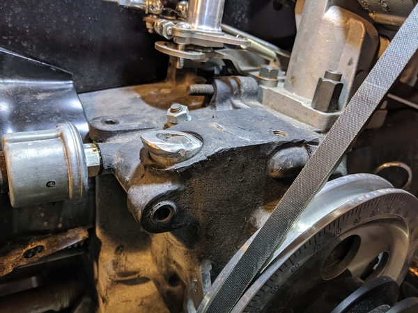
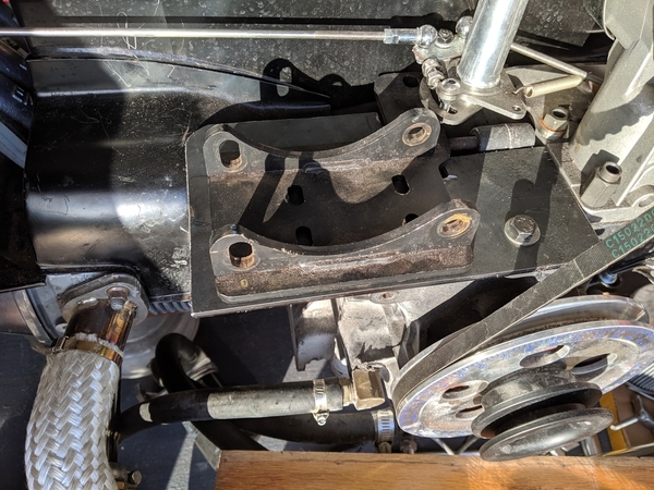
My latest update. I've converted over to totally electronic ignition powered by Speeduino ECU and a VW Golf/Passat high energy electronic ignition coil pack. It works just fine. Additionally, the carb linkage was lowered to make room for the AC compressor and I've begun to install the shoulder harness seat belts. To begin, I built a mount for the Saab 900 crankshaft position sensor (CPS). I mounted it on a case bolt on the lower passenger side of the engine. It is a VR (variable reluctance) sensor so I'm using twisted pair to the Speeduino during the test phase and will wire it with shielded two or four pair in production. The Speeduino detects TDC from the CPS when the missing tooth wheel behind the crankshaft pulley skips a beat. For those who are trying this, in my case, I configured the Speeduino to identify TDC as 92 degrees before the missing tooth. This will vary depending on how you attach your missing tooth part to the pulley and the location of the sensor. 
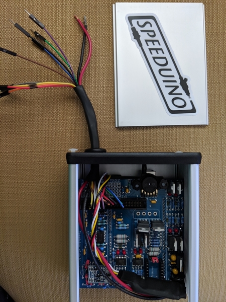
IMG_20190214_140951

The brains. Configured using Tunerstudio via a bluetooth connection. I use Shadow Dash via bluetooth on my phone to monitor it while it's running.
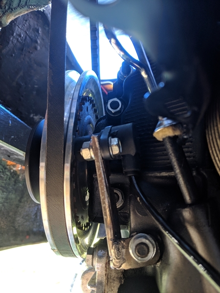
IMG_20190217_101229

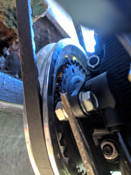
Here's a pic of the crankshaft position sensor bracket that I fabbed up. The sensor is at the top and leans in at an angle to pick up the rotation of the teeth on the missing tooth wheel I mounted behind the crank pulley.
IMG_20190217_101255

Here's a closer shot of the sensor itself. It's the black cylinder behind the shiny bolts at the top of the slightly rusty, bespoke bracket. Like I noted earlier, it leans in at an angle, but picks up the signal loud and clear.

I'm using MSD 8.5mm ignition wires with GM LS2 coil pack terminators on the coil side. They have great noise suppression as well has the ability to handle the high voltage produced by electronic ignitions. These are roughly 2 feet in length, each.

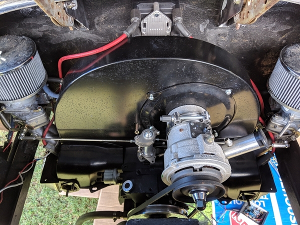
The very inexpensive Golf/Passat coil pack (part # 032905106B) is mounted on the firewall. It has 2 ignition inputs from the Speeduino and 4 spark outputs to the plugs. It is configured in Tunerstudio (software that drives the Speeduino) for wasted spark. This means that when the Speeduino senses that a spark is needed for input 1, the coil fires plugs 1 & 3. When input 2 is sensed, the coil pack fires plugs 2 and 4. For the cylinders that are not filled with compressed fuel/air, the spark is wasted, however, Jim Cortina with the Megasquirt project has bench tested this coil pack to over 13,000 rpm. I suspect it will work just fine for me. When I built my 425 hp Porsche turbo motor, I used a similar EDIS 6 wasted spark system with great results. 
IMG_20190216_130351

Wow, look at all of that empty space. Note the VW coil pack on the firewall above the shroud and the MSD wires routed out of the way of stray compressor bits. For those with discerning eyes, you may spot the lower third of a Bosch 009 that has been gutted and filled with J-B Weld. 

The upshot is I was able to remove the distributor and free up a lot of space for the AC compressor while improving the accuracy and strength of the ignition system. Total system cost was under $300. I did a lot of fabrication for this and would highly recommend the Dub Shop kits for folks who are less inclined or less patient. I thought about this fact several times during the process.

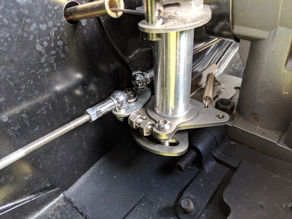
I'm using the Vintage Speed Taiwan's dual carb linkage and I decided I could get another inch or two clearance for the compressor by converting the left side linkage to a pull instead of the normal push. To do this, I make a small steel oval that attaches both the right and left sides to the attachment where the right side normally attaches (nearest the shroud). This means when accelerating, the linkage pushes the right side open (just like normal) and pulls the left side open. To make this work, I drilled and pinned the larger adjustment threaded part nearest the left carb. This allows it to be pulled. I then moved the carb linkage lever from the top side of the left carb to the bottom so the push will open the carb. Works great and is just as adjustable as the original. Now I've got plenty of space for AC. Yes, I love my wife. That's why AC is required.
IMG_20190216_130407

The little oval at the back allows both linkage arms to be driven from the rear cam.

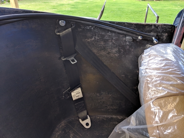
I'm installing retractable shoulder harness seat belts that I sourced from Greg and Anna at Vintage Motorcars. I've just started the installation, but have pretty much gotten my plan together. The real trick is that the shoulder belt support needs to be located higher than your shoulder to reduce the chance of injury. It's nice not to meet the steering wheel with your face, but you don't want a spine injury in exchange. I measured my shoulder height in the seat and then used a level to locate the spot on the back seat wall nearest the door that would allow an attachment with a steel backing plate. This was roughly 17.5" back from the top edge of the frame at the door. I drilled a bolt hole about 1.5" down from the top of the rear seat and then went underneath the body with various cutting tools to make room for curved plates that followed the shape of the back seat. These plates will be welded to the body frame with steel braces to reduce then chance that they'll pop through the fiberglass in an accident. The reels are attached right below the back seat lip and secured through the inverted "V" shaped steel beam that crosses the tunnel. I found that I needed to mount the reels as close to the doors as possible (and still feed cleanly). Otherwise, the mounting bolt comes out into the space where the body support heads back towards the engine. More pics on this will come later.
IMG_20190217_152217

Seat belt should harness attachment above shoulder level.  Reel is secured at front edge of rear seat, behind the driver's seat.
IMG_20190217_152015

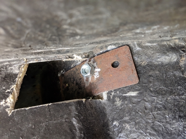
View of curved steel support behind rear seat. This pic was shot from inside the passenger side wheel well. The side fiberglass on either side of the engine had to be cut to extend the curved piece behind the rear seat. Additional bracing will be welded to the curved piece.

I know I've said it before, but thanks to everyone who has gone before and those who continue to advise and encourage. You've made it possible for seriously inadvisable projects to succeed.

Mike

Attachments

Images (7)
  • IMG_20190214_140951
  • IMG_20190216_130351
  • IMG_20190216_130407
  • IMG_20190217_101229
  • IMG_20190217_101255
  • IMG_20190217_152015
  • IMG_20190217_152217

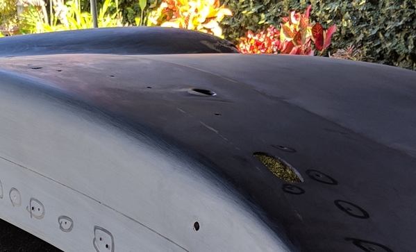
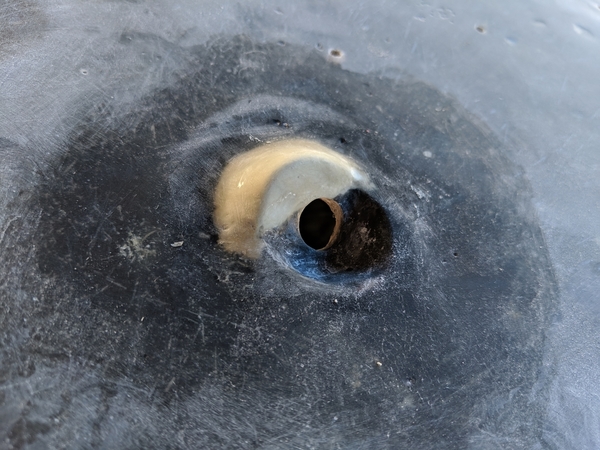
Here's help for those poor fools who have shaved all or part of the windshield wiper eyebrows off while repainting. For whatever reason, my disk sander has a magnetic attraction to the eyebrows and my reaction time is exactly in the "Oh sh*t" range. In the unlikely event that anyone else experiences this event, here's what I did to extract the bullet from my foot. no-brow

Only evidence of an eyebrow is the blonde crescent behind the hole where the wipers are attached. Note that is on the passenger side. I scrubbed off the driver side eyebrow first, said a few choice words and then went over the passenger side and did it again. This should be a caution to those who are lulled into having a good opinion of my skills and judgement.

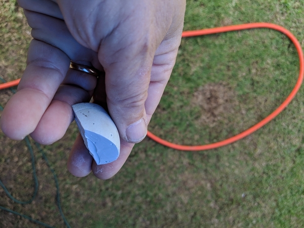
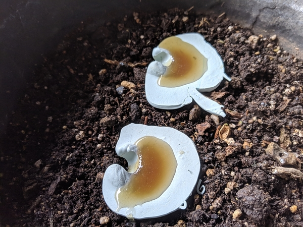
Since the little eyebrows are just a hair taller than the round washers that are used to attach the wiper system, I placed the washers in the sad gully that was left in the body and got an idea about how tall the eyebrow needed to be. I then mixed up some bondo and filled up the bottom half of an eggshell that had been sprayed with cooking spray. When the bondo egg was pretty hardboiled, I broke the eggshell off and decided it was a good starting point. I used a dremel tool to cut the half-egg into two cowl shaped parts and then trimmed off the very ends at a length that matched the shadows of the trimmed off parts. I drilled several small holes in the eyebrow piece and in the fiberglass that it would sit on. I smeared fresh bondo into the holes I drilled, applied a thin layer on top of the hood area and pressed the new piece on top. I then used acetone to wipe the piece down to help it blend in well.

IMG_20190302_140333

Part of the bondo egg left after I trimmed off the replacement eyebrow piece.

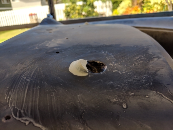
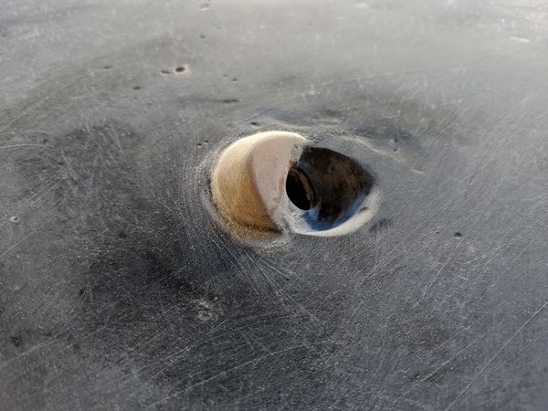
When it was dry, I use the washer to help match the angle needed on the new piece (using a dremel disk to do the cutting). I then just whittled the eyebrows down until they looked right using a piece of 120 grit sandpaper.IMG_20190302_140153

Replacement eyebrow before painting with fiberglass resin

When it looked right, I painted a thin coat of fiberglass resin on top of the eyebrows and blended them into the surrounding fiberglass. When dry, I smoothed them out using 100 grit paper in preparation for the epoxy primer painting step for the rest of the car. What a pain. Let this be a warning to those with short attention spans like me...

Attachments

Images (4)
  • no-brow
  • IMG_20190302_140333
  • IMG_20190302_140153
  • IMG_20190302_140211
Last edited by Michael Pickett

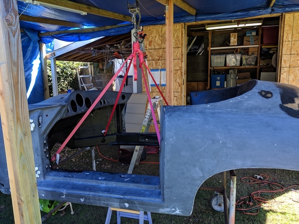
Lifting the body onto and off of the chassis. I needed to do some test fitting before painting the body so reassembling the two parts was necessary. I saw a few pics of how others had done this before and figured out how to do it "safely." The first step was to reinforce the roof above the body with 4x4s and an additional 2x6 across the top. Lateral stability was provided by additional 2x4s between the rafters essentially making a box. Swinging my prodigious weight from the rafter and making monkey noises convinced me that it was safe.IMG_20190130_140821

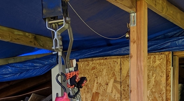
I then disassembled the top half of a come-along and fashioned a through bolt for the reinforced rafter. The come-along was attached to the rafter and four ratchet tie down straps (ratchets removed) were secured to the come-along hook.  A good pulley system with tie-offs would work as well.

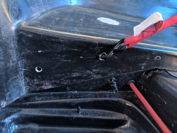
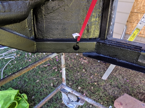
Two holes were drilled into the rear cross bar from the face of the lower package area. They need to be big enough for the hooks on the straps to rotate freely. The holes were roughly 6 inches from the outside edge of the package area. Look behind the cross member to make sure you aren't drilling into the bracket that goes to the engine compartment. Wider is better in terms of the stability of the body when lifted.  These new holes will be covered with carpet so don't sweat it.IMG_20190223_134654MVIMG_20190223_134612

The front two strap hooks will attach to the holes in the frame where the heater vents attach. Keep the front strap lengths short enough that they DON'T TOUCH THE DASHBOARD!

IMG_20190130_140829

There are two tricks to getting a level lift. The first is to shorten or lengthen the front and back pairs until they reach an equal tension level when you start the lift.  Adjust the straps in pairs (front pair and back pair). I just strummed each one and listened to the frequency of the tone (higher is tighter, lower tone is looser). Roughly equalizing the tones give you what you want. The second trick is that as you adjust the strap lengths, you should try to keep the hook on the come-along vertical (not being pulled towards the front of the car or the rear).  Otherwise, the body will swing forward or backwards when it is lifted clear.

Double or triple check everything and do a short lift. Swing the body just a little to make sure everything is secure. If you don't like it, lower it back down and adjust the straps or supports until you are comfortable with the safety of the setup. When testing, don't put yourself under anything, in case it lets go unexpectedly. I attached an extension to the come-along arm so I could stand clear when testing and it turned out to be useful leverage when lifting.

My come-along has a tab on top that needs to be flicked when you want to lower the hook. I tied some nylon survey string to the tab and ran it back outside the car so I could be clear of the body when testing the lifts and lowering. I added another string for pulling the lift ratchet back, too. This gave me more latitude when lowering (ask me if you get to this point and are confused about how that might work). The rough idea is to pull the string to disengage the handle and to raise it up near the top of its range, release the string and lift the handle slightly while pulling on the lowering tab string until it clicks back allowing the handle to get a full swing of lowering. I know, it is hard to explain...strings

When you are set up for a safe and level lift, have someone else keep a hand on the body so it doesn't rotate. We were having 40 mph gusts when I was lifting last time and the body got excited about being airborne. Surprise, you can't lower it since it has rotated out of the support range so you need to just keep it lifted and  block it somehow until you can get help. Or, you could avoid my mistake and just have someone helping. They don't need to be strong, just steady.

Alignment with the chassis attach points is important when lowering the body. Just go slow and move things a wee bit at the time. Inevitably, one corner will touch slightly before the others. Start that corner bolt loosely, it just becomes a locator peg. Swing the body until you get alignment on another corner and peg that one. It will probably help to have someone else either pegging corners or doing the slight lifting and lowering. Once you have the body square on the chassis, apply the nuts and lock it down. If it is the final lock-down, don't forget the sealing needed between the body and the chassis. Cheers,

Mike

Attachments

Images (7)
  • IMG_20190130_140821
  • IMG_20190130_140829
  • IMG_20190223_134600
  • IMG_20190223_134654
  • MVIMG_20190223_134612
  • MVIMG_20190223_134710
  • strings

Bracing for shoulder harness seat belts. I started an update on this a while back and noted that once I had located the correct attachment point for the shoulder harness (above your shoulder), I would be adding bracing since you can't expect the fiberglass to hold up in the event of an accident. 

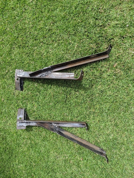
The basic idea is to make a steel plate that matches the curve of the fiberglass at the top of the package area behind the seats. The shoulder harness support will bolt though the fiberglass and then through the steel plate. Some conjecture that that would be sufficient in case of an accident. I had my doubts so I fabricated some supports out of angle iron and T iron.  

IMG_20190217_152217

Location of shoulder harness support

IMG_20190217_152015

Unsupported curved steel plate test located in area behind the passenger side package area. It is bolted through the fiberglass to the shoulder harness support. Note that some of the side fiberglass had to be opened up to allow the plate to wrap around.

braces

Finished supports: angle iron and T iron was cut, twisted and welded to provide front to back support for the curved plate. The T iron provides strong resistance to lateral movement. These are bolted to the chassis in the areas near the rear shock absorbers. They fit under or over the supports for the rear body. You may need to trim any spacers if your car has them so the supports can fit underneath. If you don't have spacers, the supports can be sized to sit directly on top of the rear body supports.

IMG_20190304_154226

Brace mounted on rear body attachment points. The brace will actually be mounted after the body and chassis are secured together since you have to do a little bit of alignment when inserting the curved plate behind the package area.

If you choose to emulate my foolishness, I highly recommend having someone who can weld do your bracket work. I know of no one who has actually crash tested a design like this and I hope I never do so. So, no promises that this is the best way to approach the problem (actually, mounting on a roll bar is the best way if you want to go that route). 

Cheers,

Mike

Attachments

Images (4)
  • braces
  • IMG_20190217_152015
  • IMG_20190217_152217
  • IMG_20190304_154226
Robert M posted:

I like reading your escapades if for no other reason than the pure humor of it all. I'm impressed by your creativity both when writing and coming up with ways to do things. Who'd have thought to go crack a few eggs to use as molds for the small eyebrow for the windshield wipers? Not me. Great job.

Aw shucks. Both my father and great grandfather were real inventors. I inherited the lack of fear to mess around with things if not the ability to convert innovation into something that puts food on the table. Second child status means I had to be the class clown to get any attention, so there you go. Now if I could just quit joking around and get this beast on the road! Seriously, thanks!

A short addendum to the wiper eyebrow saga, Ed (edsnova) cautioned me about the vulnerability of using Bondo where it isn't laying flat on the car. He also noted the possibility of the paint issues later. He suggested that I make reverse molds of the Bondo eyebrows and then fill the molds with finely chopped fiberglass (kitty fur) and resin. It felt like good counsel, so that is what I did and I'm happy with the way it turned out. Thanks, Ed!IMG_20190305_162754Bondo eyebrow w/resin shell

IMG_20190305_162902Facehugger attacks. I covered the eyebrow w/car was, stuck a tube in the wiper attachment hole and poured Bondo on top. 10 minutes later I had my mold (loosened it with a very thin paint scraper).

IMG_20190305_162951Mold after it popped loose. I then sanded off the eyebrows (again) with a longboard. Ed was right, they melted like butter.

IMG_20190305_170857Sunny side up eyebrows waiting for the kitty fur to cure. Got to keep them level :-)

IMG_20190306_110916Fiberglass eyebrow installed. It took a good bit of shaping to reduce the fiberglass piece back to the height of the original. I used a longboard with 80 grit and just kept at until it matched the empty spot on the hood.

IMG_20190308_155053

Looks even better with a few coats of epoxy primer. More on that later.

Mike
Attachments

Images (6)
  • IMG_20190305_162754
  • IMG_20190305_162902
  • IMG_20190305_170857
  • IMG_20190305_162951
  • IMG_20190306_110916
  • IMG_20190308_155053

Nice fabrication !  Probably a good idea to back up the repair on the underside with a thin gauge steel so that when you tighten the wiper nuts you're not applying all the torque at the repair. Using a thin plate etc you'll be changing the depth of the pivot out the body so be careful to check the wiper arm fit on the stud to make sure the wiper arm base doesn't make contact with the fiberglass.


Last edited by Alan Merklin

Alright, the fiberglass grinding, repair and smoothing is complete and the painting process has begun. Here's a short update. I look forward to your observations and suggestions. Thanks again to everyone for your guidance!

PAINTING GOAL
Goal is daily driver good. Skill level just ok, shot an old Porsche turbo at home 10 years ago in RI with compressor and Devilbis Finishline. I got a lot of experience with sanding out drips.

EQUIPMENT & ENVIRONMENT
Fuji mini-mite 4 platinum turbine, T75G HVLP gun with 1.3mm, 1.5mm and 2.0mm tips in temp tarp paint shed in back yard. On dry side of island with infrequent rain, temps mid-70s - 90. Humidity between mid-50s-70.

PRODUCTS
Using mostly Southern Polyurethanes (SPI) products: Wax & Grease Remover, Epoxy Primer, 2k Regular Build Primer, and Universal Clearcoat with slow activators.
Filler on top of the epoxy is Evercoat Rage Ultra.
Base coat is PPG Deltron Porsche Arctic Silver 92U with DT885 (70*-85* F) reducer

PROGRESS SO FAR
Shot 3 coats of epoxy w/1.5mm tip and the Fuji worked just fine. I used almost exactly 2100cc mixed per coat. I'm buying another qt of epoxy and activator so I'll have enough for a 10% reduced (PPG DT885) sealing coat before the base coat. I like the convenience, size and noise level of the Fuji. Turbines have a reputation for putting out a very dry, oil-free but warmer flow of air. The Fuji Platinum series has a "heat dissipation chamber (TM)" to address the issue of the warmer air. In my experience so far, it hasn't been a problem. The epoxy coat is amazingly tough - reminds me of very smooth, warm concrete. I'm thinking about painting the tarps on my paint shed with it and renting the new cottage out to island visitors :-)

TECHNICAL ASSISTANCE
I can't say enough good things about the SPI folks. They provide super high end products that are showcased at concours events, but answer the phone on the first ring and are willing to talk you through the pros and cons of every step. I grew up in NC and these guys are based in Georgia. They remind me of what southern hospitality still means in some places. They provide tons of documentation and recommendations including some that are extremely specific (like ONLY use the 1.4mm tip with Universal Clearcoat). Since Fuji doesn't make a 1.4mm tip for the T75G gun, I called and they talked me through the choices and we ended up with the 1.5mm tip and slightly reduced fluid flow (and maybe slightly higher painting speed). They said to do some test panels with the goal of wet coats with no drips - easy peasy... I felt much better and was glad that I hadn't just gone ahead without chatting with the experts.

NEXT STEPS
I've got some obligations that will put the painting on hold for a few weeks. When I get back to it, the SPI folks said to just scruff up the epoxy with red scotch-brite pads before starting the filling and sanding work. I really glad that the fiberglass repairs are complete and the car is all sealed up.

MikeIMG_20190308_160114IMG_20190308_172830

One of my buddies saw this picture and commented on my choice of using white for the epoxy coat: "These are not the droids you are looking for. Move along."

IMG_20190308_155033

Attachments

Images (3)
  • IMG_20190308_160114
  • IMG_20190308_172830
  • IMG_20190308_155033

Hey....White is GREAT!

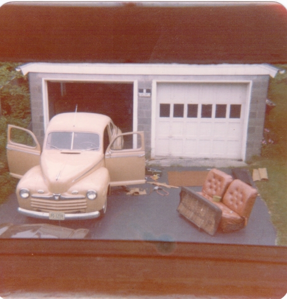
Back on January 5'th, 1974, I had just graduated college and was getting married.

BUT!  I was working on a 1946 Ford mild Hot Rod which I had gotten into Primer and sanded out during the fall semester.  I was afraid that if I left it for the winter it would rust through the semi-porous primer I had used.  I decided that, since we were moving 1-1/2 hours from my folks (and the car) the best thing was to paint it pronto and the only day I had was my wedding day.  It's a long story, but it got done by getting up at 4am and getting three coats in before 2pm with an ancient DeVilbiss pressure-gun.  Just around 2pm, my future/still wife arrived to tell me "You better get this damn thing finished or your ass is grass!"   Don't know why she was so excited -  The wedding was at 5pm.  I made it, even though we got 15" of snow between 3pm and 10pm.

It was supposed to be the color of a regular coffee but turned out a little more pink than that (1973 Lincoln Continental "Buff").  Good thing it had a bored .300 over 59A/B stroked flathead, Edelbrock dual-carb intake, Offenhouser heads, full-race cam and a LaSalle transmission - it scooted.  Still, I managed to paint it with only three runs, all of which got sanded out and looked great.  I never painted another whole car.

This was taken the following Autumn after I moved it to our apartment in Springfield, MA. to finish it.  Did the front seat upholstery on my wife's sewing machine while she was off on a business trip.      You can't really see it, but the entire seat was diamond-button-tufted.  The darker seat was the rear seat of a BMW 2002 which fit perfectly and I just covered it with the same stuff.  

The things you do for love.............

Fall 74 Coupe

Attachments

Images (1)
  • Fall 74 Coupe
Gordon Nichols posted:

Hey....White is GREAT!

Back on January 5'th, 1974, I had just graduated college and was getting married.

BUT!  I was working on a 1946 Ford mild Hot Rod which I had gotten into Primer and sanded out during the fall semester.  I was afraid that if I left it for the winter it would rust through the semi-porous primer I had used.  I decided that, since we were moving 1-1/2 hours from my folks (and the car) the best thing was to paint it pronto and the only day I had was my wedding day.  It's a long story, but it got done by getting up at 4am and getting three coats in before 2pm with an ancient DeVilbiss pressure-gun.  Just around 2pm, my future/still wife arrived to tell me "You better get this damn thing finished or your ass is grass!"   Don't know why she was so excited -  The wedding was at 5pm.  I made it, even though we got 15" of snow between 3pm and 10pm.

It was supposed to be the color of a regular coffee but turned out a little more pink than that (1973 Lincoln Continental "Buff").  Good thing it had a bored .300 over 59A/B stroked flathead, Edelbrock dual-carb intake, Offenhouser heads, full-race cam and a LaSalle transmission - it scooted.  Still, I managed to paint it with only three runs, all of which got sanded out and looked great.  I never painted another whole car.

This was taken the following Autumn after I moved it to our apartment in Springfield, MA. to finish it.  Did the front seat upholstery on my wife's sewing machine while she was off on a business trip.      You can't really see it, but the entire seat was diamond-button-tufted.  The darker seat was the rear seat of a BMW 2002 which fit perfectly and I just covered it with the same stuff.  

The things you do for love.............

Fall 74 Coupe

Brilliant. You were obviously chosen by your perfect mate, otherwise...  The car turned out great, too. Looks like cafe au lait. I may need to get you out here for some interior work at some point since you know your way around a sewing machine. I'm also impressed that you manage to find obscure seats that perfectly match your rides!

Yeah, not everything I do is all that great - Just the stuff I show on here!  

And besides....  I keep telling everyone how bad a MIG welder I am.   I'm saved by my angle grinder and thank Thomas Joseph (he invented it) every time I have to use it.  I suspect, since TIG is more like torch welding (which I'm really good at) I could TIG well, but never tried it.  

I used to be able to paint well (not great) but I no longer have the patience to learn all about the modern water-based paints and how to properly apply them.  I'm much better at fabrication in just about any material, so I leave it at that and rattle-can the finished product.  Anything that's big (like Pearl) I have professionally done.

There are a bunch of people on here who do as good, and often much better, work than I do - look at Mango Smoothie's or Ollie's work - and we all get inspiration from each other.  That's what this is all about.  People (like you, Bill) keep upping the bar.

I'm proud to say that a lot of that OCDed-ness has rubbed off on my kids who seem to be tackling interesting projects of their own.  It just boils down to seeing a need for something and deciding "I'm gonna try to make or do that".  The first few tries might be less than optimal, but you get better and more confident with each one.  After a while, you'll just tackle anything........

We've seen quite a few people develop their skills on here, and that's one of the best parts of this site!

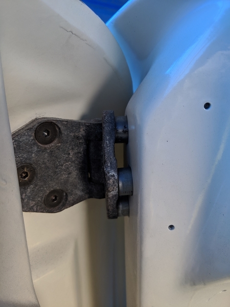
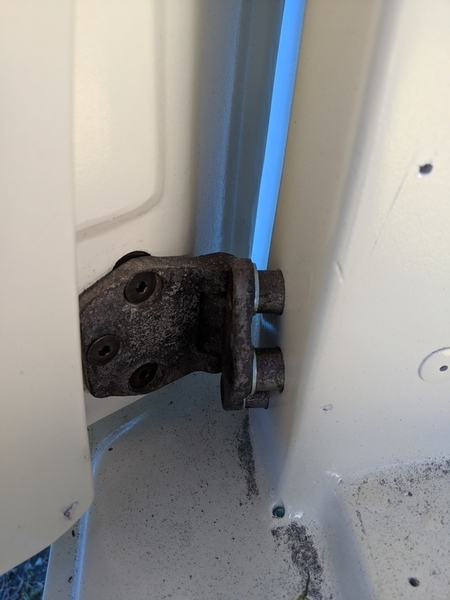
I've got a door hinge question for the CMC/IM crowd. I am missing a few of the 3/4" spacers that fit between the hinges and the supporting frame post. Is 3/4" still the recommended spacer length for all 12 pieces? I suspect that individual cars may need some adjustment for best fit, but I couldn't see whether any best practices had emerged around spacer lengths.  Thanks!

Mike

No, I think they came on the CMCs, FiberFab and old IMs. Both the FiberFab and the old CMC manuals reference 3/4" hinge spacers, but the CMC one says you can shorten them to move the door inwards. Maybe most folks had to do that. The ones that were with my disassembled car were 3/4" long more or less. I'll try it out with and without and report back.  Thanks,

Mike
Ok, back from a great 2 weeks visiting family in Japan. Every time I go I marvel at the safety, the thousands of unlocked bicycles in big cities and the general level of what we in Hawaii would call the aloha spirit. Neat folks.

I've got my IMs doors test fitted and adjusted. This forum was very helpful, but evidently a gentleman named Corey had shared a step-by-step that I was never able to find (looks like he's no longer a member (Projekt Hoopty?). Anyway, I went ahead and started the setup with 12 - 3/4" long pipe spacers between the door posts and the body side hinges. I suspect each car may have small differences depending on how the body frame jigs were set up. In my car, the body frame had been rebuilt totally, so I ended up tweaking the spacers (1/16" out on the bottom and 1/16" in on the top).  Here are the steps I followed:

Adjusting CMC/FiberFab/old IM doors

door1

  • Tape about three pieces of cardboard to the door sill.
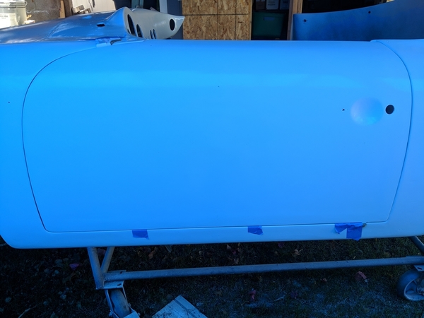
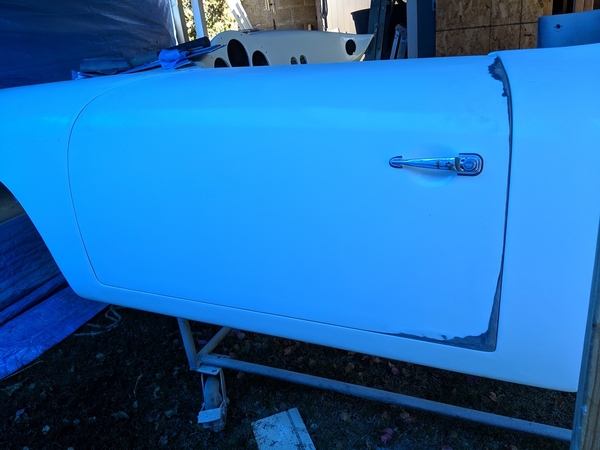
  • Sit door on the cardboard spacers and look at how the bottom gap appears. It should be level and less than 1/4 in
  • Look at the rear of door gaps and the front of door gaps. To get the door to actually fit within the door frame, it's likely that you'll need to sand off of some the rear door edge and some off of the top front inner edge of the door. Start first on the front of the door towards the headlights. look at the existing gap and try to make it consistent from bottom to top. You will probably have to sand some of the outer edge of the dashboard to allow the door top to fit flush. It's okay to carefully sand some material from the front top of the door where it touches the dashboard. Slide a piece of paper in the gap to find tight spots and mark the area that needs relief with a wax pencil. Once you have at least some small gap all the way along the front of the door, move to the next stepdoor4door5
  • Sand the rear edge of the door so that it will fit within the body frame. Don't take off too much material at this point You're just trying to get the door inside the frame.
  • When the door will fit flush in the frame on the front, back and bottom start looking at your gaps and decide where you need to take material out. Sand just a little bit at the time until you have at least a little bit of a gap all the way around. Don’t look for perfection yet and don’t take too much out.
  • Insert 3/4 inch long pipe spacers into the hinge bolt holes in the body until they butt up against the frame. Attach the hinges to the body frame and tighten firmly (small part of the hinge attaches to body, large part attaches to door).door2
  • Remove the cardboard spacer from the floor and attach the door to the hinges loosely. Rest it on something while you line up the bolts and bolt plates. Remember to use two short bolts on the top of the top hinge. Tighten slightly until the door can still be moved but will hold the position.
  • Try to close the door and then do some gentle adjustments to the bottom gap and the front & rear gaps. Loosen and tighten the hinge screws as needed to shift the door.
  • Once you can get the door within the frame, work on getting an even bottom gap - 1/8” or so.
  • Once you have a fairly even bottom gap, see if the bottom of the door is even with the edge of the body. On both of my doors, it was sunk a little inwards from the body along the bottom edge gap. If it is inward, you will need to add spacers on the body side of the small pipe spacers to move the bottom hinge outwards. If the bottom edge protrudes past the body, you will need to grind down the pipe spacers 1/16th inch or so.door6
  • Before removing the hinges, take a pencil and mark around the sides and front of the hinges where they currently are located. This makes it easier to get back to your starting point. Remove the bolts from the hinges and take the door off. If the bottom needs to come out, add three flat washers to the screws attaching the hinge to the body at the bottom. If the bottom needs to move inward, remove the pipe spacers and grind off around 1/16th inch from each one.door3
  • Reassemble the door hinges hand attach the door again putting the hinges back at the marks you made.
  • Close the door and check the bottom gap again. Repeat the adjustments as needed until the bottom is flush. These adjustments will alter the flushness of the top of the door and may squeeze out any gap you had along the top (sand a small amount if this occurs).
  • Check the top of the door and see if it leans out from the body or leans into the body. If the top of the door leans out from the body then you will need to take the pipe spacers out and grind them down a 16th of an inch or so to help move the top back in. Keep adjusting the top spacers and the bottom spacers until the door is flush at the top and the bottom.
  • Once the top and bottom are relatively flush, you can finalize your edge gaps. Recheck your gaps all around the door at this point. You're on the final leg now and can use fine adjustments to the hinge positions and edge sanding to achieve the gaps you want
  • If you have done all of the adjusting and have achieved good gaps and flushness with other body surfaces but still have one corner or part of a door edge that sticks out, you will need to sand the surface of that corner until it matches the body outside of the door. I run a paint stirrer across the gaps to see if it strikes an edge that is sticking up. I mark those spots with a wax pencil and then open the door and sand across the edge to lower it.door9
  • Don’t look for perfection. If you are doing these things, you’re going to be doing some touch-up or a total repaint. There are opportunities in the filling/painting stages to make the surfaces match up well.
  • A final important step: drill two small nail-sized holes in each hinge where it attaches to the door. Go all the way through the hinge, the fiberglass and the bolt plate. Label/mark and keep each hinge with its matching bolt plate. Mark the side of the bolt plate that faces the hinge. This way, using nails/pins in the locating holes, you can return to your alignment on any particular door if you have to take it off (say for painting) in the future. Keep each hinge/plate pair in a separate, marked zip lock bag to be sure they don’t get mixed up.door7door8


Have a great weekend everyone!

Mike

Attachments

Images (9)
  • door1
  • door2
  • door3
  • door4
  • door5
  • door6
  • door7
  • door8
  • door9

I have been summoned by a mysterious email saying I’m still here. 

I’m not, really. I’m on the facebook page, but not here — partially because of stuff like this. Navigating this site, with a tub of people using made-up names, is not my cuppa.

I can’t find what it is I’m mentioned in or what the relevant connection to me is with a door hinge (which looks really nice, by the way), so I’m headed back to the hermitage.

if you need me, please use the phone. :-)

Last edited by Cory Drake
Cory Drake posted:

I have been summoned by a mysterious email saying I’m still here. 

I’m not, really. I’m on the facebook page, but not here — partially because of stuff like this. Navigating this site, with a tub of people using made-up names, is not my cuppa.

I can’t find what it is I’m mentioned in or what the relevant connection to me is with a door hinge (which looks really nice, by the way), so I’m headed back to the hermitage.

if you need me, please use the phone. :-)

(and get off my lawn!)  

You can get used to "new things" if you really try, @Cory Drake

Last edited by Stan Galat
mppickett posted:
Alan Merklin posted:

Mike can you post a photo ?

Sorry, I just started a visit to the Osaka/Kobe area of Japan. Not much car progress for another week or so. IMG_20190315_200343

Alice and I arrived at  this station a couple of years ago.  Stayed at the hotel across the street. So upscale and crazy-busy.  Enjoy your trip!


Cory Drake posted:

I have been summoned by a mysterious email saying I’m still here. 

I’m not, really. I’m on the facebook page, but not here — partially because of stuff like this. Navigating this site, with a tub of people using made-up names, is not my cuppa.

I can’t find what it is I’m mentioned in or what the relevant connection to me is with a door hinge (which looks really nice, by the way), so I’m headed back to the hermitage.

if you need me, please use the phone. :-)

I guess scrolling up a few comments was too hard.

Anyway, Mike the job you did looks fantastic. I'm going back to Facebook too where there are just as many people with made up names but since they're my friends I know who they are. Oh wait! I know who everybody is on this forum too, even those with made up names.

Sounds like exciting times back when the board changed software. Incidentally, @Theron, I don't have a problem navigating or searching (although I sometimes am clumsy in finding). Nice job and many thanks for keeping this place running. I was one of the first non-Harvard Facebook users back in aught-6 and still have a love/hate opinion about it. I didn't know about the speedster owners group and have signed up for it on there, too. You can never get enough speedster info. Thanks for the kind words regarding the little door set up post. Truth be told, with my memory these days, I might be someone who benefits from it. Cheers,

Michael Phillip Pickett (Mike, please)

Mike,

I've been Cory's friend for years. He can get cranky when he hasn't had his Metamucil and morning constitutional. Plus, he found some crabgrass and two dandelions in the yard this morning, and getting the sprayer out is going to eliminate his nap.

I think you have it all figured out, but he's a good dude with a hangover grudge that has nothing to do with you or anybody else on this site. Losing all his build pictures in the migration from Theron's old site to this one makes him super-reluctant to engage over here. Pity, though-- IMHO, the FB format makes continuity of thought a lot more difficult. Plus Mr. Zuckerberg has a tendency to root around in places he ought not be.

It's a big tent, and there's room for both spaces.

Last edited by Stan Galat

No troubles at all, Stan. Cory said my door hinge looks really nice so he's obviously got good taste :-) Seriously, while looking for door info I came across a lot of his old Projekt Hoopty work and saw that he has amazing skills and creativity. I'd be upset, too if I lost a lot of things I cared about. I was actually delighted to find out where he's hanging out now. It would have been a shame for the community to lose the kind of knowledge that he obviously possesses. Re: FacePlant - if you want to see a million pictures of the most beautiful and talented 2 year old on Maui as well as examples of a warped sense of humor, just look me up there. I occasionally post speedster build updates on my wall, but nobody really understands what I'm doing. I'm in total agreement about the trustworthiness of the Zuck. It's just business for those guys.

I like the tone, friendship, humor and supportive folks on this site. Having to keep thousands of faculty members happy (all smarter than me and each other) for several decades means I just don't get offended easily so please rest assured that I'm just fine. Thanks for your explanation and humor, though. It's always good to understand what is going on with folks around you.

Mike

RevellHi, Mike. Cory again. I went back and re-read what I had said a couple days ago, then what followed. Sorry about being so curt.

I do like what you've done, especially the part where you took a great deal of effort to explain how the steps related to each other, and how each step of your process is built upon the last. Marking nails and using them as guides is brilliant, as is your writing on how and why.

The only thing I would add is to color-code top, middle and bottom. I put paint on everything, but in order to make the different pieces make sense, especially with the different pieces of pipe as spacers, that's what I'd do. Red-yellow-green or something, before they get bagged in the future (like you said, for paint or patch-work).

As has been pointed out, I did record all of my advice to "future me" here, from my wiring diagram and fuse arrangements to wheel offsets and sources for parts. I was counting on the old  site to be my archive, and most of my critical stuff was in the captions for my build's photographs. I didn't have a reliable computer at that time (2005-2007), and was spending long hours every day I wasn't at work literally buried in a garage. It was quite a lot of information, and none of it got saved in archival form.

I think it's safe to say my entire build was documented here, from the time I cut into the body with a reciprocating saw and threw away my perfectly good Speedster seats, right up to the day I did a burnout leaving the garage. 

It's all probably searchable, but there're just hundreds of posts and thousands of detail photos out there -- floating around -- and searching them out is like throwing darts into a lake to catch one particular fish. I find it frustrating, moreso because I'm old enough now that I'm beginning to forget things I know I typed up.

Stan and Danny have brow-beaten me sufficiently. I've got a little more time than I did the last time this came up, and maybe a little more patience. Your efforts are much cleaner than mine were. You're writing with brilliant style, and I think I might just have to settle into a comfy chair now and again and check in on what's happening here.

No promises, but thank you for doing interesting things.

Attachments

Images (1)
  • Revell
Cory Drake posted:

Revell

Cory, thanks man. Glad to see the Hoopty is still looking good. That's a great idea about a touch of paint on things to indicate position or order. I'll definitely take that approach before final paint disassembly. I've moved onto fitting the luggage compartment cover and latches.  Thanks again and hope to see you around here or on the FB group. Your projekts are great inspiration.

Oh, as a postscript, I've become addicted to Google tools (Chrome, Keep for lists, Docs, Sheets and Photos). Since I use a Google phone and Google Fi is my carrier, every photo I take is automagically backed up to Photos. I dummy up my SOC posts in Docs and then just copy/paste to the website. I've lost enough stuff in my life to just want backup done without ever thinking about it.

Mike
Last edited by Michael Pickett

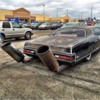
So, it's getting to be decision time on several key rebuild issues. The hood, dashboard layout and the exhaust. I'd like to share my preferred approaches and would appreciate well considered opinions and criticisms. Remember, my goal is a serious tribute to not only the greatness of the 356 speedster, but also the long, serious racing history of Porsche. 

4694644940_0facbbbaed_zI've pretty much settled on this steering wheel and gauge set up, but let me know what you think.Another-Cardboard-Car

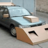
So, don't get me wrong, I think the rear end aero is just wrong, but I have to say that the front end and hood treatments might give me the extra 10ths of a second that I need in street mod 2.

exhaust

Okay, now I'm really conflicted about the exhaust system. I've narrowed it down to either this one or another, totally different approach.

lHk8IN7-655x436I have to say that I am a little bit inclined to go with this approach since it's likely to give me the best clearance over speed bumps. 

Like I said, I'm struggling here and could use some good advice. Some days I don't even know what day it is I'm so conflicted. Thanks!

Mike
Attachments

Images (4)
  • 4694644940_0facbbbaed_z
  • Another-Cardboard-Car
  • exhaust
  • lHk8IN7-655x436


Mike, I think this is the better option:

exhaust

While it doesn't appear to be the 'four into two into one' extractor design that's preferred for our engines, it will probably be free-flowing enough for anything under about 20 liters displacement. The only downside is that heater boxes will be very expensive.

And, despite appearances, the other one is not a legitimate exhaust system:

MoreExhaust2

This was an early attempt by Mercedes to get their turbo diesels to run as cleanly as Volkswagen's. Only one of the 24 pipes is connected to the engine. The rest are fakes.

The thinking was that there was only a one in 24 chance the smog station would test the actual exhaust pipe, so you had a 23 in 24 chance of passing your smog test. If you failed, you could just bring the car back the next day and what are the chances they'd pick the right pipe twice in a row?

From an engineering perspective, this is actually a much simpler solution than what VW came up with.

Have a nice April.


Attachments

Images (2)
  • exhaust
  • MoreExhaust2

And... he's back. First the trip to Japan and then having the flu (brought home by my wife and the 2 year old from art class) and finally a few weeks in NC to attend 3 family reunions. I'm finally back to my "fighting" weight, or at least my TV binge watching weight.

It's getting warmer out here (around 70* in the morning and 90s in the PM). I've made some progress with body filling and sanding the hood and fenders, but the Evercoat Rage Ultra sets up too quickly in the warmer temps. I've taken a break on the body work and have some of the Rage Ultra Xtra being delivered today. They claim setup times at around 20 minutes, so I expect I'll get at least 10 minutes before my puddle becomes a lump.

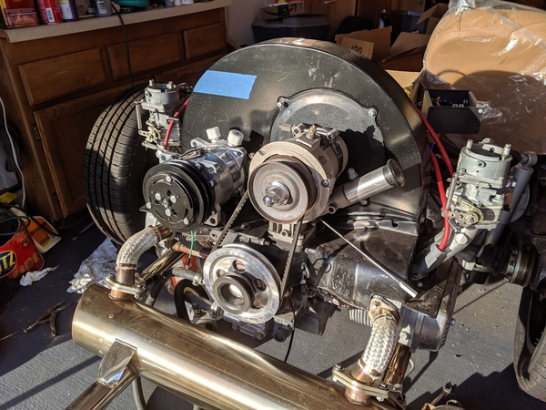
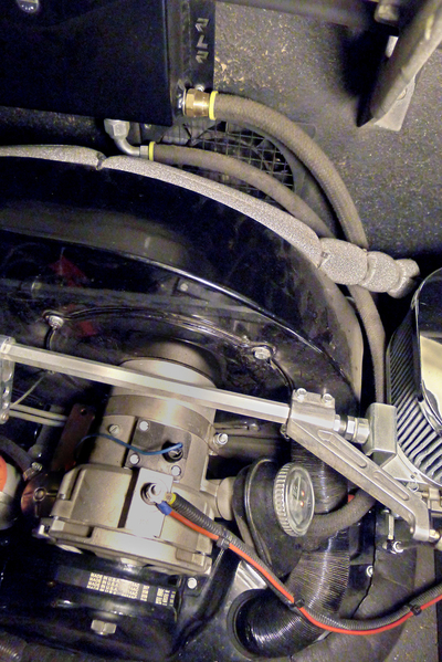
In the meantime, I've been fabricating a mount for the Sanden SD7H14HD AC compressor (model 4647). As you may recall, I removed the distributor and setup electronic ignition to open up a space for the compressor. During the body test fit, I marked the fan shroud with blue tape to indicate the highest point the compressor would fit under the deck lid. Here's a few pics of what I put together. It's way under the top limits and I'm happy with the fit. I ended up using a fractional horsepower v-belt (read lawn mower). If anyone needs something like this, NAPA carries them with a part number of 4L300W (1/2" x 30"). If you need slightly different lengths, a 31" belt would be 4L310W and so on. Amazon carries a variety of lengths from D&D Powerdrive with part numbers 84300 (30"), 84310 (31") etc.

The condenser and fan will be located between the back seat area and the firewall. I had two long hoses made up (14.5' of #6 and 19' of #10). It cost me $280 and made me regret selling my AC hose crimping tools before retiring out here on the island. But, how many more times will I be doing this, right Alan?

Here's the open space where the distributor used to be. I plugged the hole with a cut-off distributor shaft filled with JB Weld. I cut the shaft at an angle to provide additional level space for a mounting plate. The distributor clamp bolt can be seen in the middle. It's at an angle, so I fabbed up a bracket that followed the angle down to the edge behind the oil pressure sensor. That bracket then angles up to the end of the mounting plate and the whole support bracket welded to the bottom of the mounting plate. This adds additional thickness to the plate and horizontal rigidity.

openspace

Below is a test fit of the mounting plate. A 1"x1" notch was later cut so the bolt in bracket underneath could be easily accessed after the bracket was welded to the mounting plate. The plate is 3/16ths thick. I suspect the bracket underneath adds enough rigidity to keep anything from vibrating. Time will tell, I've had some interesting sounds emerge from supercharger brackets that 'should' have been just fine :-)

mountplate

Below is the Sanden bracket laid on top of the mounting plate. In this picture, it is turned 180* from where it should be. You want the long ears closest to the center so you can add tension to the belt when you are adjusting. Once I got the bracket where I wanted it (so the drive belt and compressor would be correctly aligned), I center punched and drilled four holes in the mounting plate to match up with the Sanden bracket.

bracket

Test fit of the compressor. The blue tape marks the highest point that the top of the pulley would clear the deck lid. We're way below the interference line and a shorter bracket should put less stress on the mounting points.

spacetospare

Final mounting setup with everything set up with loctite, adjusted and tightened. Phew, this setup was one I've worried about for a while. It turned out to be easier than I feared.

finished

I may need to clean up the engine a bit before I finish. It's showing a little bit of what happens when you live close to the beach and have 20 mph winds every day.

Attachments

Images (5)
  • bracket
  • finished
  • mountplate
  • openspace
  • spacetospare

As you may have seen on the news, Maui has been burning since yesterday. We're fine and there hasn't been much property damage, but our town was cut off from the rest of the island yesterday (roads in & out closed). I donned my good filtration mask and finished filling/sanding the body. Here's a picture of the second guide coat. I'm much happier with the progress at this point, although I may be approaching the 40 hr limit...

IMG_20190712_133517

Attachments

Images (1)
  • IMG_20190712_133517

Mike,

Regarding the belt-- if you find that the belt you have doesn't handle the load of the compressor, the 4L300 you have is the same width and length as an A28 (which has a much higher horsepower rating). 4L-series belts are fractional horsepower rated and A-series belts are made to transfer quite a bit more power. I've got no idea what an A/C compressor draws, but if you need more, a suitable replacement is readily available. 

Any industrial supply store (Grainger, et al) carries A-series belts for industrial fan, etc. applications. I see that you have a "green" belt, which is the Gates brand lawn and garden 4L belt, if I'm not mistaken. As an aside, I greatly prefer Gates brand belts to anything else. I've found that a Gates 4L-series belt will handle as much power as a Browning A-series belt.

Looking good on the project!

Todd M posted:

@Michael Pickett - I was watching, "Iron Resurrection", and they were doing body work on a Vette.  Shorty, their painter, explained that body work on fiberglass was difficult because sanding tends to make hills and valleys.  I had never heard that before.  What has your experience been?

When I was removing the rotten paint and damaged gelcoat I tried using various power sanders. The disc ones were particularly prone to making valleys and the flat oscillating ones were better in some places. Our cars have so many curves it is tough for a non-professional with limited intelligence (me) to get good results with power tools. My bro-in-law built sports fishing yachts for a few decades and swore by his air power file, but I decided that I'd just get a bunch of rubber sanding blocks and build up my biceps.

I've done more fiberglass sanding than I want to recall.  On flat surfaces you can use a long board sander on all other areas I use a rubber sanding block. Light guide coats  of primer is a must do. 180   220   320  then final with epoxy filler primer . and sand that too. Unless you have a lot of experience with a air DA , I would not suggest using one . Lastly that stuff is extremely dangerous and you need long sleeves gloves, a good ventilation set up and a quality respirator mask and goggles. 

Last edited by Alan Merklin
Stan Galat posted:

Mike,

Regarding the belt-- if you find that the belt you have doesn't handle the load of the compressor, the 4L300 you have is the same width and length as an A28 (which has a much higher horsepower rating). 4L-series belts are fractional horsepower rated and A-series belts are made to transfer quite a bit more power. 

Stan, I should have thought to ask here about the belt. My decorating sensibilities were offended by having a lawn mower belt in the engine bay. It made it feel more like a toy than I was hoping. Now that I've got the right size, I can order an A28 and use the Gates as a spare. Thanks!

Alan Merklin posted:

I've done more fiberglass sanding than I want to recall.  On flat surfaces you can use a long board sander on all other areas I use a rubber sanding block.

Alan, I find myself switching between a hard rubber block and a softer block or rubber rod when the curve is concave and the rectangular hard rubber block doesn't easily fit. Any warnings about using the soft rubber block?

Thanks

mppickett posted:
Alan Merklin posted:

I've done more fiberglass sanding than I want to recall.  On flat surfaces you can use a long board sander on all other areas I use a rubber sanding block.

Alan, I find myself switching between a hard rubber block and a softer block or rubber rod when the curve is concave and the rectangular hard rubber block doesn't easily fit. Any warnings about using the soft rubber block?

Thanks

I know that the thin rubber block ( pads) tent to allow too much finger pressure , can  that telegraph those impressions onto the sanding surface.  Guide coats are a tell all.


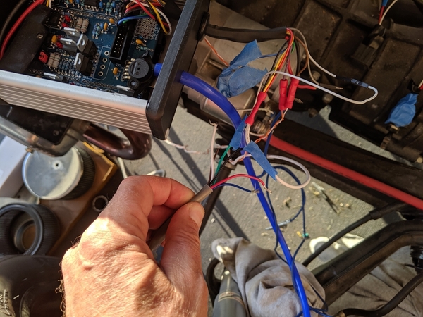
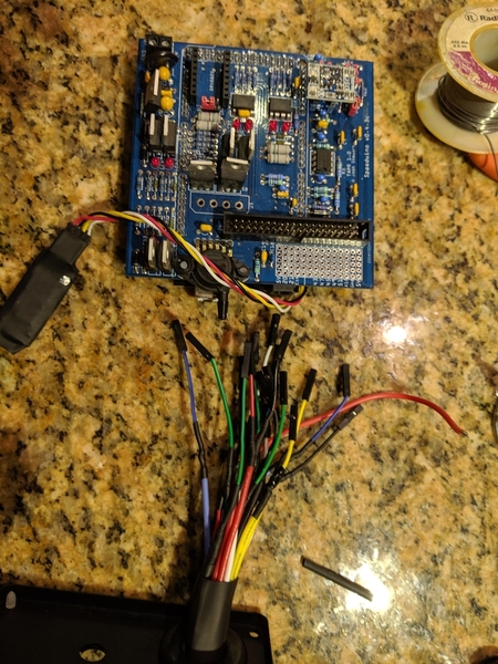
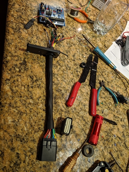
Took a break from the Bondo and guide coat world. Do you know how long it takes (me)  to design and build a custom engine control unit wiring harness? One whole day. The tricky parts were making sure it was waterproof since the ECU will live in the engine compartment and guessing what functionality I might want to implement in the future (fuel injection, idle/choke control, etc). The ECU supports 40 pin outs but I was able to get away with a 20 pin waterproof Molex connector since I don't plan on ever turbo/super charging the engine. 

Right now, I'm only implementing spark and air/fuel mixture monitoring, so most of today was "just in case."

Marianne and I got married when we were in college and we worked to support ourselves. I worked as a medical prototypes electronics technician so I got to dredge up some 1970s technology and skills. Not a speed demon, obviously.

Before:

IMG_20190715_182815

After:

IMG_20190716_191229

IMG_20190716_191222

Attachments

Images (3)
  • IMG_20190716_191222
  • IMG_20190716_191229
  • IMG_20190715_182815
Last edited by Michael Pickett
mppickett posted:
Todd M posted:

@Michael Pickett - I was watching, "Iron Resurrection", and they were doing body work on a Vette.  Shorty, their painter, explained that body work on fiberglass was difficult because sanding tends to make hills and valleys.  I had never heard that before.  What has your experience been?

When I was removing the rotten paint and damaged gelcoat I tried using various power sanders. The disc ones were particularly prone to making valleys and the flat oscillating ones were better in some places. Our cars have so many curves it is tough for a non-professional with limited intelligence (me) to get good results with power tools. My bro-in-law built sports fishing yachts for a few decades and swore by his air power file, but I decided that I'd just get a bunch of rubber sanding blocks and build up my biceps.

Admittedly, I watch a few car building tv programs, and at least during the filming it appears that they do most of the sanding without power tools.  It seems they use different size sanding blocks with the longer ones bending.


mppickett posted:

...I'm thinking about mounting something on the firewall...


Maybe a good time to mention that the top of the firewall is usually considered the best place for an oil breather (if you were thinking about putting something else there).

Mounting a breather high makes it easier to give the output tube a steady, downhill run to wherever it's going. And a breather with enough volume to work well takes up more space than is available just about anywhere else in a Speedster engine compartment.

My VS has about five inches between the firewall and fan shroud, and the oil breather takes up about half of that.


SpeedsterBreatherHose02


Attachments

Images (1)
  • SpeedsterBreatherHose02
Gordon Nichols posted:

Oh, so NOW all these posts show up.......  After I ran back from CAPE FRIGGIN COD early just to help out a fellow Rhode Island GoomBah with measurements since no one else had posted.

Thanks, you'se guys.  I could still be sitting on Craigsville Beach, watching Bikinis.   

Above and beyond, Gordon. When you come to see the finished product, I'll show you the beaches where you can watch bikinis (or I can point you to the beach where bikinis are optional).

Sacto Mitch posted:

 Maybe a good time to mention that the top of the firewall is usually considered the best place for an oil breather (if you were thinking about putting something else there).

Thanks, Mitch. I'm thinking about putting the ECU and the Golf ignition module on the firewall since they really don't match with the look of the type 1 engine and I wanted to keep them out of the rain. You make a great point and I will plan accordingly.

Mike

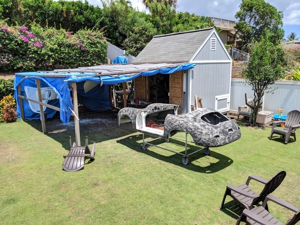
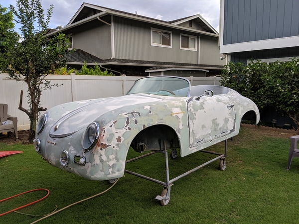
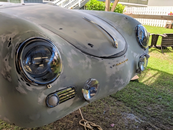
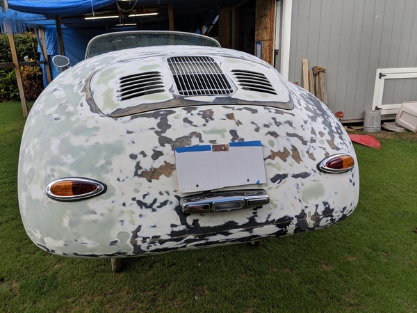
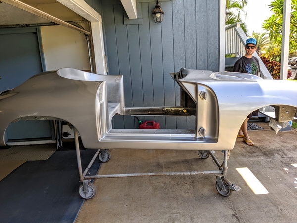
Progress is being made. Because Maui has been having brush fires covering over 10,000 acres (arson, they've arrested the firebug), there's just tons of ash and junk blowing around. The block sanding, gap setting and test fitting is done and it's ready for the final paint steps. I am sending it and the paint out for the final steps rather than wasting my time and materials in this mess. 

Here's a few pics before I send it off.

IMG_20190730_165837IMG_20190730_130524IMG_20190730_165903IMG_20190730_165155

My assistant is pretty good at taking things to other people and riding in the body when I move it around. 

Hopefully the next pictures of the speedster will be a bit more attractive

Mike

Attachments

Images (5)
  • IMG_20190730_165837
  • IMG_20190730_130524
  • IMG_20190730_165227
  • IMG_20190730_165903
  • IMG_20190730_165155

@ALB I thought the same thing and went back the page 1.

"We decided on silver paint and tan top/interior. I like the mild outlaw look, so it won't have bumpers and side trim. It came with silver fuchs that will be refinished with the black background, silver spokes Carrera look." 

@Michael Pickett I am cannot wait to see it come back from paint and on the road enjoying a beautiful Maui sunset.

I got mine painted by a local place highly recommended by the Hot Rod guys and they did a fabulous job.  Even though I was at a financially advantageous time in my life, it was still a bit of a shock at the cost of 8 gallons of paint; 4-coats base, 2-coats pearl and 3 coats clear at around 2 Grand just for the paint!  It's no wonder I don't paint a lot of cars...

I find the time to go back to where it was painted every year (I'm about due....Right after I get the Dells back into shape) and show them that, even after 21 years, now, the paint looks like it was shot yesterday (yes, the front clear bra helps a lot to keep it looking good).........  Except for the spot where my gardening rake fell on it a while back in the garage.  

Well, Mike, it was a gravel rake that fell from about 5 feet higher than the body after I slammed the outside door on the same wall.  Made my stomach turn, for sure and the rake now resides in a gardening shed, rather than the garage.  I don't get stone chips on the nose, so I guess it had to be something.  

So, Mr. Pickett - Who's the Autobody Assistant and part-time Yard Pilot?

Last edited by Gordon Nichols

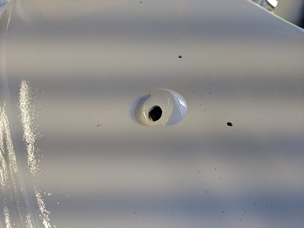
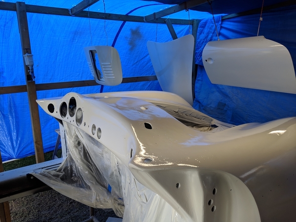
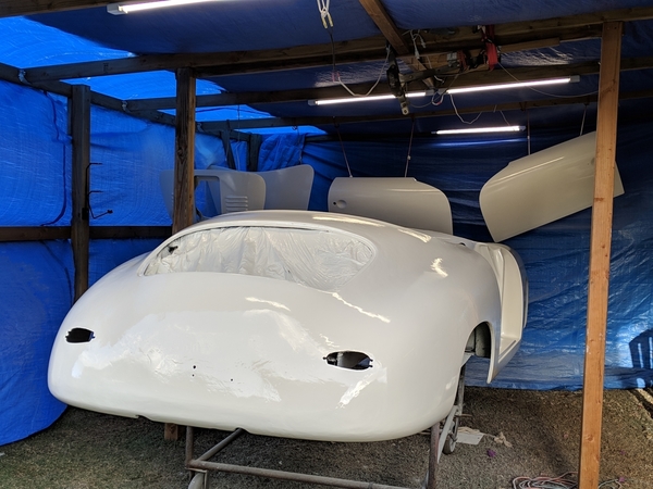
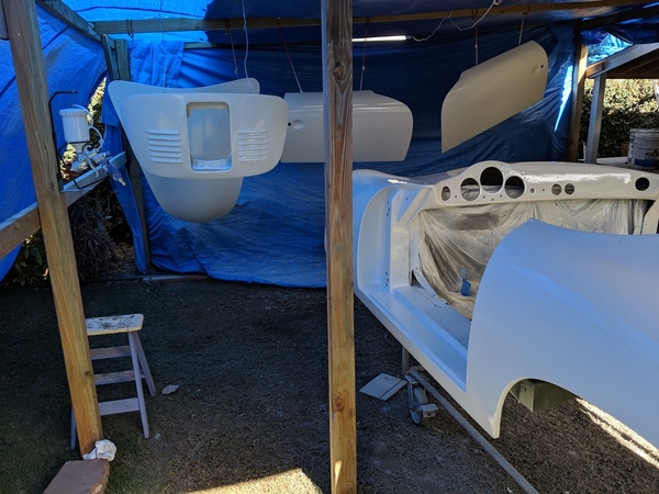
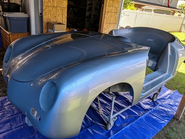
Tons of progress. Most importantly, the body just got back from the painter and he did a great job. This last week I've been finishing up the tasks that have to be done before the body is bolted to the chassis. Even more important, Marianne decided to help me clean up the 40 year old aluminum pieces that goes under and over the windshield! Several hours later they looked great!!!

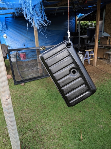
The wiring harness for the engine is built, the alternator hookup and circuit breaker is installed, the carburetors have been synchronized and tuned, the floorboards have been painted with POR15 (rust prevention) and bracing for the seatbelt mounts fabricated. Plus, the oil cooling system has been assembled and the new super-sized gas tank has been scrubbed and internally sealed. It's been a busy week with lots of progress!

My son, David inspects the paint job:

IMG_20190820_120321

Wheeled around to the backyard house of tarp for assembly and lifting onto chassis:

IMG_20190820_121301 [1)IMG_20190820_121337IMG_20190820_121406

Engine tuned, sensor, ECU and ignition module wiring harnesses completed, alternator circuit breaker and charging circuit completed and oil bypass completed for assembly with body:

IMG_20190817_151427

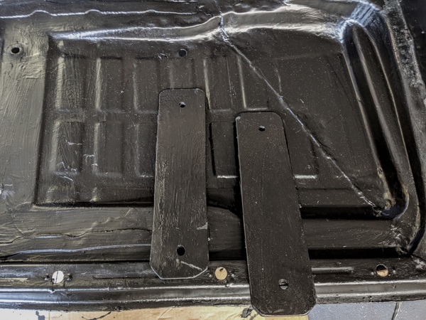
Floorboards recovered with POR15 (whole chassis has been treated now). Two oblong 3/16" steel reinforcement plates cut and POR15'ed. They sit under the floorboard and the rear seatbolts pass through them. They make me feel good about tying the seatbelts to the seat frames (important so that the seatbelts fit my 5' 11" frame as well as Marianne's 5' 2" (with an updraft) frame):

IMG_20190818_102346

Marianne decided to find out what all the fun was about and cleaned up the 40 year old windshield frames. They're nice and shiny now!

IMG_20190818_111133

Finally, cleaned and sealed the new super sized gas tank. What the heck, gave the outside of it a coat of POR15, too. The screen door in the background just rated regular ACE anti rust:

MVIMG_20190811_164710

Thanks again to all of you guys for your encouragement, ideas, help and mirthful comments. It's been a full year since we dragged this thing into the backyard and I'm feeling like I can see the finish line.

Mike

Attachments

Images (8)
  • IMG_20190820_120321
  • IMG_20190820_121301 (1)
  • IMG_20190820_121337
  • IMG_20190820_121406
  • IMG_20190817_151427
  • IMG_20190818_102346
  • IMG_20190818_111133
  • MVIMG_20190811_164710
Last edited by Michael Pickett
Post Content
×
×
×
×
Link copied to your clipboard.
×
×