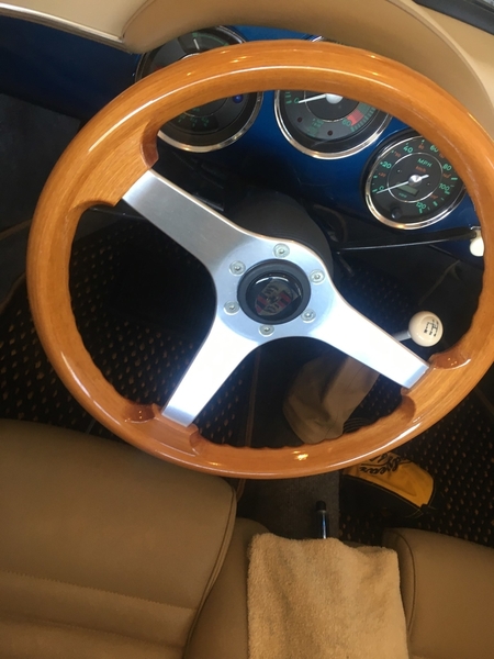
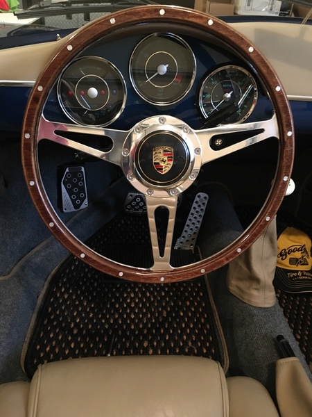
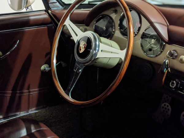
The pics below show my old steering wheel and horn button and my new ones. I love the new setup.
Replies sorted oldest to newest
Super nice !
That's excellent!
Where did you get the wheel?
Are you weeely asking him that? 'Bugs bunny voice" calling the bear on the cycle ![]()
It's really a "piece of art" unto itself! ![]()
Here's Marty's without the rivets and with hidden fasteners and rounder button...
I like both.
Yeah those wheels have been tempting me for a while, but I don't really want a P crest on the wheel.
Very nice, Jimmy!
That new wheel looks so right. I really think a nicely made, period-correct looking steering wheel is one of the best upgrades one can make on one of these cars. It just feels right, and it really amps up the legitimacy factor, to me.
One of the first non-safety-related things I did on Bridget was replacing the stock Grant 14-inch wood rim—which isn't a bad wheel at all—with this outrageous 17-inch replica Bluemels Brooklands banjo wheel as found on MGs of the period.
I actually hesitated. At nearly $400 all done it was a ridiculous expense!
But it changed the whole character of the car. It absolutely transformed it from "obvious kit car" into "hold on, what is this stunning old machine doing here on a busy city street?"

Now, some guys don't like that old time thin grip, the large diameter, the sometimes flimsy feel of the old banjo spokes, and I get that. A chunkier, modern wheel is absolutely worlds better, ergonomically. But they just aren't art.
Jimmy's new wheel is Art.
Marvelous, absolutely marvelous.
(As said in your best Billy Crystal replica voice)
Thank you for all the nice comments, I agree it is a work of art and makes a huge improvement.
I bought the entire wheel, adapter and horn button with home made Porsche crest button from James (Jaime) from his classified listing here on SOC for $375.00 all in shipping included. I thought it was a very reasonable price.
I need help now getting the horn to work. Alan maybe or someone else with infinite knowledge can give me some direction. My old wheel and adapter had the horn setup in a one wire system. The wheel adapter had a copper ring in the base that was isolated from the rest of the adapter with a wire going to the horn button. The copper ring was in contact with copper half round fingers on the top of the steering column and this is the 12 volt power. The outside of the horn button was the ground via the wheel, adapter and steering shaft. When the horn button was depresses the circuit complete and the horn blew. The new adapter doesn't have the copper 12v pickup ring but the adapter does come in contact with the 12v contact fingers on the steering column and immediately completes the circuit to the ground which is the steering shaft and horn blows non stop soon as the adapter is in place. For now I have the horn wire disconnected. The new horn button has two wires instead of one. How is the new horn supposed to be hooked up? how do i pick up the 12 v signal without using the copper contact system? Does what I described make sense to anyone? Thanks in advance. Diagrams with your descriptions appreciated.
@edsnova posted:That new wheel looks so right. I really think a nicely made, period-correct looking steering wheel is one of the best upgrades one can make on one of these cars. It just feels right, and it really amps up the legitimacy factor, to me.
One of the first non-safety-related things I did on Bridget was replacing the stock Grant 14-inch wood rim—which isn't a bad wheel at all—with this outrageous 17-inch replica Bluemels Brooklands banjo wheel as found on MGs of the period.
I actually hesitated. At nearly $400 all done it was a ridiculous expense!
But it changed the whole character of the car. It absolutely transformed it from "obvious kit car" into "hold on, what is this stunning old machine doing here on a busy city street?"
Now, some guys don't like that old time thin grip, the large diameter, the sometimes flimsy feel of the old banjo spokes, and I get that. A chunkier, modern wheel is absolutely worlds better, ergonomically. But they just aren't art.
Jimmy's new wheel is Art.
Ed, how does that wheel feel when you drive? Do you feel like it turns faster?
Jimmy look at this ... https://www.speedsterowners.com/topic/horn-wiring
@IaM-Ray that wheel makes me feel like the captain of a large freighter ship during the War of 1812 and this could not be more appropriate.
What i need it a thin flat ring of copper sheet with a thin sheet of insulating material bonded to one side and a wire soldered to the copper. This commutator ring we will call it will sit in the bottom pocket of my new wheel adapter and come into contact with the hot 12v commutator on the top of my steering shaft replicating the way the setup was designed to function on my steering column which looks to be out of a 71 beetle. This was the correct way to make the horn work without having a wire twisted and spun over and over until it eventually breaks and shorts out. This is the way my old after market wheel and adapter was set up. I will be looking to see if the commutator ring I described is offered for sale before i commence fabricating one. I will keep you informed. Thanks for the info. It appears this is an old issue many have had.
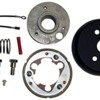
After my first search using steering wheel adapter 1971 vw beetle I found this. I believe one of the items in the kit is the commutator ring I need.
Attachments
I think i figured this horn thing out. I have the wrong adapter for my steering column. The link below is the adapter I need as you can see the copper bottom to make contact with the 12v horn power as it is delivered on my steering column. The one without the copper inlay bottom is the one I have now which is wrong the pic. of the other is what I need. I guess I will be ordering the correct adapter.
https://www.flashpowerparts.co...-audi-vw-beetle.html
Attachments
@Jimmy V. May I ask - have you experimented with the connections.... mocked up the wiring to test you can make the horn button work? I ask because a few continuity experiments may save you from buying a new hub. All you need is some wire and clips to test,
do you have a picture with of how you have the set up connected? pictures of your hub + adaptor + wiring + horn...
the picture you posted above - by flash power - is not for an adaptor, but for a new hub. ( if you decide to buy a new hub, do you know what column year/ size you have? Early VW columns come in 3 sizes... different diameters and number of splines...) the ground will make contact throw the splines, the 12v through the cable that come up the column - the cable that likely connected to you old horn button.
How did you go from a one wire set up to a two wire set up? Did you use a horn button adaptor? Or have your replaced the hub.
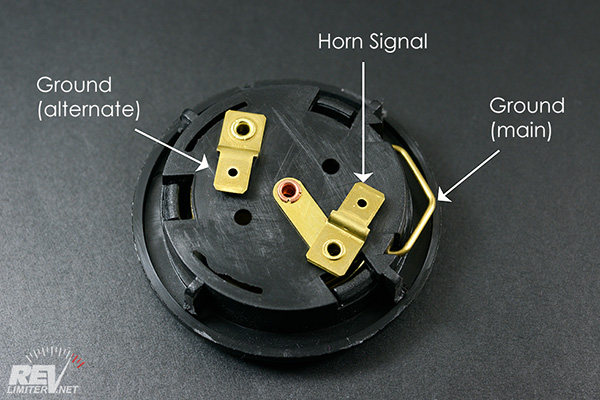
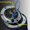
if you used and hub adaptor.. often times a horn ring adaptor is needed if the horn button needs two wired ( does not have a ground contact that relies on the hub for the ground. Reference pic.
not knowing what set up you have:..
- it’s common to have a one wire horn system where the ground comes up through the column.
- horns come in three flavors. Ref picture below.
a) horn signal wire + ground ( main)
b) horn signal wire + ground ( alternate)
c) horn main wire + ground main + ground alternate.
Q 1- which horn did you have before? Lets assume a)
Q2- what does the new horn look like. B) or c)?
Q3- did you change the hub? Or did you use a hub adaptor to go from your old 6 hole set up to the new 9 hole wheel set up? Lest assume you used a hub adaptor,
Possible fix Scenario 1:
if your new horn looks like a) or c) and you used an adaptor... your horn should work correctly if you have good contacts at the ground and the signal. ( only honk when you press the horn).
it will stay on/honk only if the circuit is closed... when the ground and signal are making continuous contact, ie:
- is the horn signal wire making contact with the hub/ horn ring after you push it in? . sometimes pushing the horn to far into its resting place... the hub adaptor.. can close the circuit, not requiring the button to be pushed in to close the circuit and honk continuously. I found this out the hard way once.,.. Will get back to this in a second,,,
if you have horn style B) you may need a horn button adaptor to connect a second cable and close the ground circuit. ( like in the picture above).... but unlikely as most 6bolt to 9 bolt adaptors fit snugly and you can close the ground circuit by bending the ground clip to touch the hub adaptor,
test the wiring before you connect the horn: a good test to perform after your hub adaptor has been installed, AND before attaching your horn... is touching the wire to your hub. This will make you horn go “beep beep”. This will let you know your wiring and hub/ adaptor are working well.. all connections are made, and are now ready to introduce your horn into the test equation.
depending what horn you have you can now test for continuity before pushing in your horn into the adaptor... By connecting the hot cable, and using a second to close the circuit with the hub. if your horn works as intended you know the wiring and the horn works, and the problem is introduced when you push the horn into its resting place in the hub adaptor.
One way to test if the hot wire is making contact with the hub ( before you press the horn button) after the horn is pushed in...put some electrical tape over the horn signal connector after you connect the cable and before pressing it in to insure it can’t make contact with the hub. The test... press your horn button,,,hopefully it all works as designed.
there are multiple other scenarios,... all depending on what set up you have, & what may have been done since you disconnected the working system... tracking down why the circuit is closed before you buy new parts would be where I would start.
...but this note is getting long... happy to help, but a would need a bit more details... pictures are worth 1000 words.
cheers,
Luis
Beautiful setup ..congrats, looks fantastic,


