Hello friends...just put in FAT 2.8 liter Type 4 in my VW pan based CMC speedster kit. I am getting strong opinions on to be or not to be putting a rear motor mount in. Really do not want to break anything with the torque this motor puts out. Any experienced or otherwise opinions on this subject?
Replies sorted oldest to newest
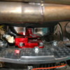
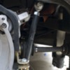
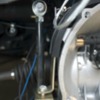
If you search a thread here titled "Monster 2.8L type 4" you will see that I have had a 2,8L type4 engine built for my VW pan based Puma. I have Kafer bar braces on the transaxle the same as many including myself use with Subaru engines attached to VW transaxles and it works great. Do you have Kafer style bar braces on your speedster? How many HP did Fat say your motor has? I am curious to compare it to my build. Can you let us know the build specs of your motor? The left bar was bent to allow clearance of a type 1 engine's header that I had been running in the car. The transaxle is a rhino cased Rancho pro suby trans axle.
Attachments
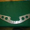
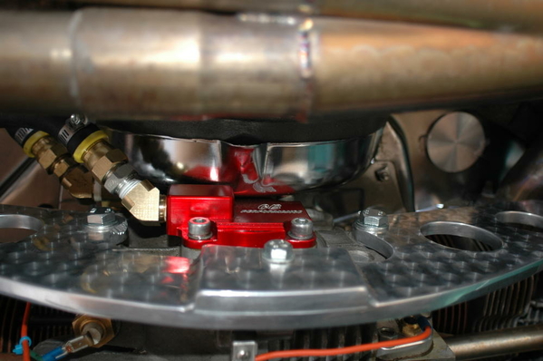
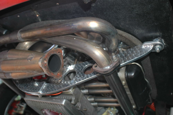
Are you thinking along the lines of a rear mount out of a mid '70's VW bus? A rear mount, especially for a heavier type 4 engine, is never a bad idea if the car has enough structure to support it. A member here, Bruce from California, built this aluminum mount for his Speedster. It's lightweight (it could use a few more holes, but I digress), quite elegant and (I think) does the job very well. I don't see why you couldn't adapt his design- 
Attachments
I would also be really tempted to add a transaxle mid-mount brace to keep the front (nose) of the transaxle from trying to lift up under hard torque/acceleration. T-4 engines are torquey buggers and they can rip a nose mount to shreds pretty quickly. Gene Berg makes a nice, rugged one and there are others around (aircooled.net)
The Beck boys are running Rhino front mounts just for that reason. Me, too.
If you look at the pic in my last post my Puma setup has a rhino mount also. I have had good luck using that mount. My Suby Speedster has one also, it was converted by Special Edition. They know their stuff form many years of trial and error finding what works and what doesn't.
Jimmy V........I know you are very astute at doing the wrenching on your cars but I couldn't help but notice that, in my opinion, the lower attachment of your Kafer Bar to your trans saddle is a weak point. Those two tabs should be eliminated or welded to the trans saddle. I envision that with the entire assembly jerking around from the tremendous amount of power you have will unscrew one of the big nuts on the end of your mounting horn. Please don't get insulted by my critique. Only trying to be helpful.
Here's how mine were..........Bruce
Attachments
I have thought the same by looking at the way this is set up. This is the way the kit comes and is supposed to be installed. I have this same Kafer setup on my Suby Speedster and it was installed this way by Special Edition during the conversion. I am not insulted in the least by your comments. So far my setup has proven very rigid and sturdy and done the job it is supposed to do. I have done 2000 plus rpm clutch drops on the Puma with the a type 4 and a 2276 type 1 engine without a single issue. If it becomes a problem going forward I now have a remedy, thank you for the input and sharing of your knowledge.
I chuckled at your trial by fire. "2000 rpm clutch drops". That's exactly what I did as well..........some even at 4000...........Bruce
CoolRydes has a nice lager bar setup and so does CB Performance now. I believe the CB one is based on the one from Eyeball Engineering before he passed away.
The Type 4 has so much power it didn't need more than 2000rpm drop to full throttle to free spin the tires to redline in 1st, 2nd and 3rd gears maybe 4th as well but I stopped at 3rd gear as I had moved slowly forward and sideways about 50 ft. in 20 or so seconds. Point is it didn't need more than that to get the tires in a super spin condition.
@Gordon Nichols posted:I would also be really tempted to add a transaxle mid-mount brace to keep the front (nose) of the transaxle from trying to lift up under hard torque/acceleration. T-4 engines are torquey buggers and they can rip a nose mount to shreds pretty quickly. Gene Berg makes a nice, rugged one and there are others around (aircooled.net)
The Beck boys are running Rhino front mounts just for that reason. Me, too.
I forgot about the mid mount- thanks for catching it Gordon!
And for those that don't know- the very functional yet elegant rear mount pics I posted belong to @aircooled- he's the Bruce I was referring to.
Good morning Bruce! Al
5000 190........200
5500 188........179
On Sunday, January 3, 2021, 11:43:34 PM PST, SpeedsterOwners.com <alerts@crowdstack.com> wrote:
[New Reply] rear motor mount for 2.8 liter FAT type 4 in VW based Speedster
| == To reply by email, write above this line. == |
| |
|
New Reply By Jimmy V.
|
| rear motor mount for 2.8 liter FAT type 4 in VW based SpeedsterReply by Jimmy V.
If you search a thread here titled "Monster 2.8L type 4" you will see that I have had a 2,8L type4 engine built for my VW pan based Puma. I have Kafer bar braces on the transaxle the same as many including myself use with Subaru engines attached to VW transaxles and it works great. Do you have Kafer style bar braces on your speedster? How many HP did Fat say your motor has? I am curious to compare it to my build. Can you let us know the build specs of your motor? The left bar was bent to allow clearance of a type 1 engine's header that I had been running in the car. The transaxle is a rhino cased Rancho pro suby trans axle.
This post contains 3 images.
[ View Reply ]
|
|
| | Unlock Premium Membership
$49.00 Per 12 Months, plus tax if applicable |
|
| SpeedsterOwners.com - 356 Speedsters, 550 Spyders, Replicas and more
You received this based on your notification settings. You can adjust your settings or unsubscribe anytime.
------------------- Speedsters For Sale -------------------
------- www.DrivenToys.com ------
|
Thanks for the info on your engine. Are the HP numbers wheel HP from a chassis dyno or flywheel Hp from an Engine dyno? Can you give me the actual cam specs? I can't find any info on a FC444 cam. What valve sizes do your heads have? What type of header and exhaust are you running? I am very interested in your engine because of having a similar one. What stroke is your crank and what size are your Pistons and cylinders? Thanks in advance.
Jimmy,
Sorry, I don't have any more details on the cam and FAT is now gone. Send me your e-mail address and I will send pics of build sheet? and dyno readout...it was taken on engine dyno. I have Coolrides/Mendeola kafer bar kit and rhino nose mount mounting a beefed up Rancho highway flyer 3.44 r&p with a 3.78 first gear so far. Coolrides/Mendeola also sells a neat mid tranny brace that I haven't installed yet...still working of 50 other things. The exhaust consists of FAT's stubbies and A-1 custom fab exhaust system. Bruce's custom fab aluminum mount (from this thread) is exactly what I am looking for!!!!(will be trying to contact him) but will be a trick (ha ha) fitting anything with exhaust system and engine tin. Keep in touch...where are you?...
Gary Hafner San Diego
My email is sales@federalknife.com
Rimco bought what was left of FAT Performance, and the company is now called FAT Performance Rimco.
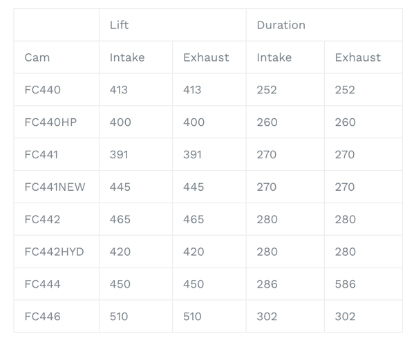
On page 15 of the "Products" portion of their website is "Type 4 Performance Camshafts". There are 8 different options of FAT T4 camshaft available.
Attachments
Stan , Thanks...people like you keep sites like this and their followers in the know!
Are you an employee of them? Just wondering how they are doing?
Stan most certainly does not work for any of the manufacturers. Although, he does seem to be singlehandedly supporting($$$$) some of them!
FAT/Rimco are in the west, Stan lives in Illinois.
586 degrees of exhaust duration. That’s a neat trick! Lol
I saw that too, funny! What's 300 degrees between friends or engine parts
My cam is a Webcam 86b/86C split duration cam with .501 lift intake 300 duration and .510 lift exhaust with 310 duration. My compression ratio is 9.5:1
Attachments
@DannyP posted:Stan most certainly does not work for any of the manufacturers. Although, he does seem to be singlehandedly supporting($$$$) some of them!
FAT/Rimco are in the west, Stan lives in Illinois.
Now you're just being hurtful. ![]()
I'm nobody, @Gary Hafner-- a pipefitter from Nowhere, USA. I've just been in this hobby a long time, and stuck with it mostly because I'm a simple(minded) man, and don't have the mental bandwidth to get bored easily. Maybe someday, I can find my niche and make a retirement hobby business of all of this nonsense, but at this point I'll just keep shoveling money into the boilers of progress on the consumer side.
Along the way, I've watched builders and suppliers come and go and have always tried to take note of what's happening. It's a funny little dead-end on the automotive evolutionary tree. It's a good idea to keep tabs on who's still out there slogging away.
They're getting fewer and further between.
Gary...Here's all the photos I have left. Yes, weaving it thru the headers to connect it to the 2" square support tubes was fun. You do have to remove some of the headers to R&I it. One photo says it all....CAD (cardboard aided designed) then a wood mockup to make sure it fits and you can install it and finally the real deal. If I did it again I would insert and weld nuts into the bottom of those 2" tubes rather than using all-thread all the way thru to the top of the tube. R&I would be easier this way because I could just remove those bolts with the rubber isolators and the bar would be free to slip out.....Bruce
Attachments
My apologies for asking again, Bruce, (I remember asking before but I'm not sure of the answer)- what thickness aluminum did you use, and what was the reasoning for doubling up the center section?
And I know I've said this before but- this was a great approach to the problem. You made it functional, lightweight and it looks great!
Thanks Bruce.
"And I know I've said this before but- this was a great approach to the problem. You made it functional, lightweight and it looks great!"
Oh- I forgot to add "although it could use a few more holes!"![]()
@ALB posted:what was the reasoning for doubling up the center section?
Even if Bruce has forgotten more than I'll ever know-- I know why.
The mounting bosses on the front (rear) part of a universal case T1 engine are not "in plane"-- some of them stick out further than others. I did this on the one I made as well.
Thanks @aircooled and @Stan Galat- I figured it was something like that. Bruce (and Stan)- do you think (in retrospect) that 3/8" plate was necessary or would 1/4" aluminum have done the job? And Stan- would you mind posting a pic of the rear mount you built? I know you've shown us before, but (since we're on the topic) it would be nice to see it again.
Sorry, @ALB-- I built 2 of them years ago, but I have no idea where they are now. I'm sure I scrapped the heavy one, and the other was just a ridiculous bit of over-engineering.
Al ....The only reason I went with 3/8" material is it got rather narrow and small out at the ends where the bolts were attached and I didn't know if there was going to be a lot of stress there. In retrospect, 1/4" , T-6061 aluminum would probably be fine.
Stan....... thank you for the complement ! However, CRS is more the likely cause of my memory loss !
As you all know, my next toy is all Subaru drivetrain and I'm looking forward to new adventures in getting things just the way I want them. Probably won't need a traction bar but I'm sure there will be other fun things deal with. Still haven't made up my mind about a heater yet so maybe I should just put in some "tee's" now just in case I do want one.Wheel and tire size for the rear are still a mystery yet too.
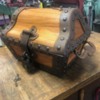
On another note, while being "carless" I have been busy building a "Treasure Chest" to fit in with the motif of my office/mancave. It weighs in at 84 lbs. empty. The Oak is 1.5" thick and the iron cage around that is 3/16" X 2". The pistol in the lid is a 58 caliber double barrel flintlock. This gives you a second chance to foil your captors who are forcing you to open your chest and steal your treasure ! Har Har Har !
Enjoy.........Bruce
Attachments
Wow!
Avast ye mate-es... that be a chest worth sailing some serious oceans for!
Bruce Et. al experts... got to fabing a rear engine mount a la Bruce's design...thought it was going to be fun...but rear (back) of Type 4 has 4 possible mounting posts tightly around the timing pully ...which will make it interesting...but three questions:
1.It would make it very friendly if I were to use only the bottom two posts...is it worth risking ? As mentioned I have excellent "Stiffy" kafer bar, rhino front mounts and a CoolRydes "flop stop" mid-mount.
2. If all 4 make safe sense...the top right mount looks to have a allen wrench nut plugging the threaded hole. If I remove this...will all my tires deflate and napalm flow out? or is it suitable for mount attachment?
3. How big/thick a rubber stop/ring/donut would be ideal for frame mount interface?
Staying safe in my garage....Gary
Gary.....Since my universal case had 3 threaded boss's I just assumed that the engineers thought it was necessary to keep from ripping apart. My thoughts are that there is a lot of torque applied when you want to launch your car and those mounts have to hold it back. Perhaps 3 bolts would be enough ?
Bushings. Very important ! Must be hard rubber ! My logic says these are necessary criteria to be able to withstand compression from the torque load and isolate noise transfer from the drive train back into the body. This means that there should be an inner lip on the bushings so that the thru bolt doesn't touch the torque bar. Shock absorber bushings (usually the top ones) from many different cars are ideal for this.
Summit Racing (under rubber bushings or rubber bushings for fabrication) has a lot to choose from for these. They don't need to be thick bulky ones that would have a lot of "crush". I used shock bushings and sliced them to half their height. You need to use them on both sides if your torque bar to provide acceptable noise isolation. The nice part about the torque bar is it's long and reduces the amount of torque applied to the frame. In essence, the reverse of using an extension handle on a torque wrench or a torque wrench multiplier.
I hope this helps you Gary. Let us know on here and post some photos too......Bruce
My universal/type3 case has those 3 holes as well. Two are 10mm and the third is 8mm. There was a rear motor mount attached to those holes, similar to a 911 rear engine carrier. But the type3 was less than 60 hp, right?
I did make my own engine mount on my first Spyder(but it's in the front). It prevented the motor from torqueing upwards, the reverse of the Speedster which twists downwards. I recommend you install the mounts in compression. I used Vanagon motor mounts, they are a pretty stiff rubber, about 1.25 to 1.5" thick, with an 8mm stud on either side. It worked well with close to 180hp and HARD launches.
I can't use it any more, due to my dry sump pump sticking out about 4 inches. But the delrin bushing for the trans and HD bellhouse mounts with a metal strap ove the bellhouse works great.


