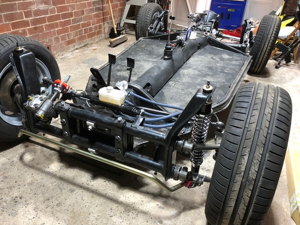
Yup, Beam adjusters (I prefer the Avis version) on the front beam are spiffy for doing that final fine-tuning, regardless of normal or drop spindles.
I wrote the article below a while back and it is up under the "Resources/Knowledge Base" tab at the top of this page. That version has photos, but here is the text for you, with the very handy table for setting ride height. It shows you how to adjust up or down in 1/4" increments.
Remember, that it is fruitless to try to set ride height on just the pan - you really need the car completed, engine in and all that jazz, to get it set up right. Otherwise, you'll just be in there re-setting it after the car is complete because it won't be where you want it. Also, the balance, left to right, is set by varying the height of the left or right rear as the car sits, so, again, you'll need the car completed to do that. Resetting ride height on an assembled car isn't all that difficult, and it can be done in less than an afternoon. Here's the article (I hope the formatting carries over from my service manual). The process is identical for swing-arm or IRS cars.
One last thought: You CAN go the route of adjustable spring plates on the rear to do any adjusting, but you may still have to adjust the plates on the torsion bars to get into a preferred range for the adjustable plates to give you what you want. I don't have adjustable plates since I just set my normal plates up to where I wanted - And I haven't touched them for over ten years now.
3.2.8 Setting Rear Ride Height
Detailed instructions here (you may need to be a Supporting Member to see them and the photos):
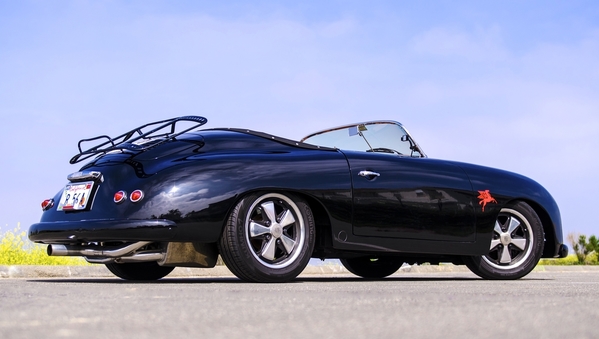
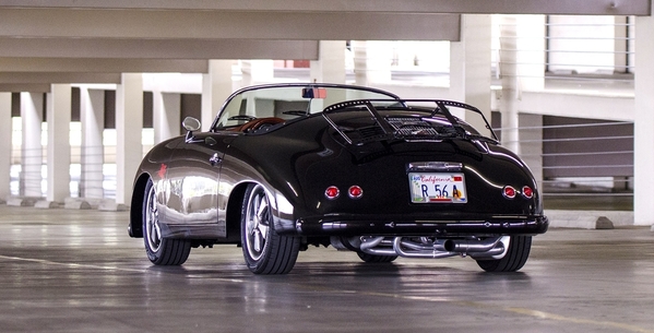
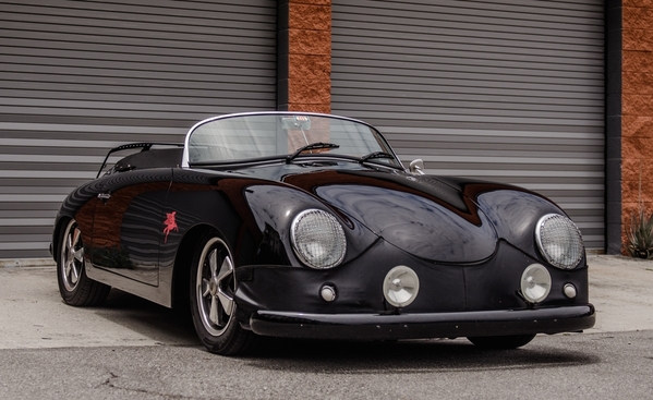
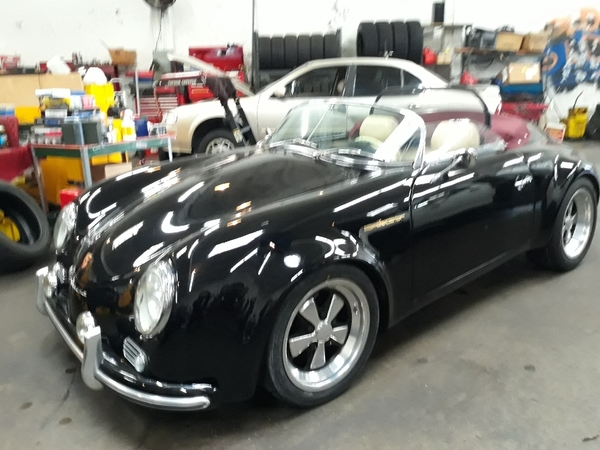
Adjusting rear ride height on a Speedster Replica
This article should give you enough information for you to re-set the rear ride height on a VW pan-based Speedster, regardless of whether it starts out high or low and regardless whether it is an IRS or swing-arm suspension (although we’ll be showing IRS suspension in this article). The job is relatively simple (and what isn’t simple on a pan-based car?) and should take about two to three hours to re-set BOTH sides.
Make sure that your car has settled the suspension by either driving it around or rolling it back and forth across a 20 foot distance a couple of times. Start out by measuring the distance from the ground to the top of the wheel well arch on both sides and write them both down. When I started on mine, the passenger side was sitting at 23-7/8”, while the driver side was a mere 23-1/4” A difference of about 1/2”!
Once you have the starting heights, you’ll need to decide how you’ll adjust it. In my case, the passenger side will be left alone and I’ll raise the driver side the needed 1/2”
We’ll start by getting the car up on Jack Stands such that it is comfortable to work on and securely stable. Once that is done, remove the wheel on the side(s) you’ll be working on for access to the suspension, and then remove the shock absorber and put it aside.
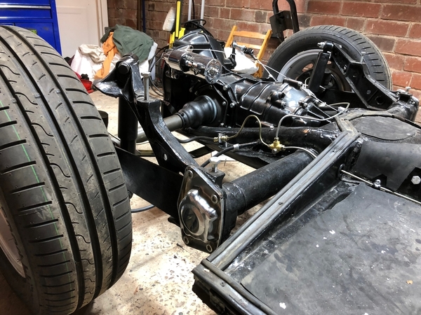
The rear hub is attached to the spring plate by four bolts. Before you touch any of them, use a metal scribe to outline the hub casting where it attaches to the spring plate, and make a line mark on both the hub casting and the spring plate to reference later on for alignment. I used a cold chisel a while back and marked both permanently (look close to see the mark). On my car I have a rear sway bar attached, so the hub mount for that must be removed along with the spring plate bolts, as shown (just swing the bar down out of the way once it’s been let go on both ends).
Once the alignment mark is made, go ahead and remove all four bolts. Be careful in case your hub is loose between the spring plates, but it usually stays put. Now loosen the four bolts holding the torsion bar end cover in place - back them out 1/2” or so to allow the cover to move out. Place a floor jack under the bottom end of the spring plate(s) (use a wooden block between jack and plates) and slowly jack it up until the inside plate just clears the stop on the torsion bar mount, then use a small pry bar to gently coax it outward and then slowly lower the jack to allow the spring plate to swing down beyond the plate stop. Remove the torsion bar cover.
Find a socket that will just fit through the big hole in the torsion bar mount so that it’ll prevent the spring plate from moving up in the next step. Use a socket extension as a handle and hold it in place while you do the next step:
Put a floor jack under the brake drum (use a wooden block between jack and drum) and jack it up until it clears the spring plate - it should be free of the plates.
Scribe a line along the top edge of the spring plate onto the torsion bar mount as a reference of your start point.
Now for a little info on how the rear suspension is adjusted: Rear torsion bar inner and outer splines are different. Inner splines move 9 degrees per spline, while outer splines move 8 degrees, 10 minutes per spline. Measuring my car (a 1969 Beetle pan with IRS) gives 17 inches between the centerlines of the torsion bar and the axle, so using C = pi(D) you get a circumference circle of 106.814 inches (imagine drawing a big circle with the torsion bar center at the middle and the axle centerline at the circumference). Break that up into degrees and its .297 inch per degree and .005 inch per minute.
Applying the math gives one inner spline (9 degrees) for 2.673 inches of axle travel (either up or down), and for one OUTER spline (8 degrees, 10 minutes) you get 2.426 inches of travel (either up or down). Using combinations of inner and outer splines allows a little less than 1/4" travel at a time by going one way with an inner, and the other way with an outer.
Here’s a table I did to save you all that math:
Table 1:
U = UP
D = Down
Inner - - - - - - - - Outer - - - - - -Result (inches)
1D . 2.673 . . . . . 1U 2.426 . . . . . . D .244
2D . 5.346 . . . . . 2U 4.852 . . . . . . D .488
3D . 8.019 . . . . . 3U 7.278 . . . . . . D .741
4D . 10.692 . . . . 4U 9,704 . . . . . .D .976
5D . 13.365 . . . . 5U 12.130 . . . . . .D 1.235
6D . 16.038 . . . . 6U 14.556 . . . . . .D 1.482
7D . 18.711 . . . . 7U 16.982 . . . . . .D 1.729
8D . 21.384 . . . . 8U 19.408 . . . . . .D 1.981
9D . 24.057 . . . . 9U 21.834 . . . . . .D 2.223
10D . 26.730 . . . . 10U 24.260 . . . . .D 2.470
11D . 29.403 . . . . 11U 26.686 . . . . .D 2.717
12D . 32.076 . . . . 12U 29.112 . . . . .D 2.964
13D . 34.749 . . . . 13U 31.538 . . . . .D 3.211
14D . 37.422 . . . . 14U 33.964 . . . . .D 3.458
Ok, so in my case I have to move the car UP 1/2”, so the spring plates must move DOWN 1/2” at the rear axle. Pretty simple, but I will also be sitting on the driver’s side, so I’m going to increase ride height a little more than that for my weight - say, 3/4” or so. Looking at the table, I need to go three splines DOWN on the Inner end, and three splines UP on the Outer end.
Now for the trickiest part of the job, because you want to do each end of the torsion bar separately, but not screw up one end while adjusting the other. Let’s start on the inner splines first: Grasp the spring plates and the torsion bar end cap and apply a sideways pressure to them by using the spring plate as a lever so as to keep the outer end from coming loose on the torsion bar. Now rock/jiggle the torsion bar out of the inner splines but do it gently so you can feel when it just lets go. Now gently press it back in to feel the splines and move it in the desired direction - in my case I have to move the inner splines 3 up, so I gently start to move the spring plates up, feeling each spline until I get to three, then I push the torsion bar back in as far as it will go.
Now for the outer splines: Again, grasp the spring plates and bar end cap and gently wriggle it around to work the end cap off of the end of the torsion bar. When you feel it let go, gently hold it in place and rotate it in the desired direction - in my case, I now need to go three splines down so I rotate while gently pressing on the cap and spring plates to feel one, two, three splines down and then push the end cap onto the splines, but not yet all the way on.
For the next step, you’ll need a small container of Baby powder with which to “lubricate” the torsion bar bushings. The inner bushing is held captive by detents in the housing, so all you’ll need to dust is the inside of the bushing and/or the outside of the end cap where it inserts into the torsion bar tube bushing. Be liberal - dust it up nicely white, then push the end cap all the way on/in. For the outer bushing, grasp it and slide it outward on the end cap tube, then liberally dust the tube and slide it back into place, then dust the outside of the outer bushing as well as the inside of the end plate. You can then slide the end plate onto the end cap.
If you’re not using new spring plate bushings at this time, then the end plate should slide on far enough that it’s bolts will thread into the torsion bar end mount. If they do not reach, you may need to go get four new bolts the same size and thread pitch and about 3/4”-1” longer to get everything started. Simply thread the new bolts through the end cover and into the casting and tighten them so that the cover goes on far enough to, one by one, replace the longer bolts with the proper ones. Get them threaded in, but do not yet tighten them down.
Re-position the wheel hub flange between the spring plates and gently slide it down more-or-less into place. You may need to use a small pry bar to get it in between the spring plates again, but it should fall right in.
We have to get the spring plates back up onto the bottom stop of the torsion bar mount. To do that, place a wooden block onto your floor jack and position under the rear end of the spring plate and jack it up until the bottom of the plate just clears the stop on the mount. Now, tighten the four bolts of the end cap cover a little at a time in a cross pattern to keep it even until all four are tight. Torque them to 30-35 ft. lbs. Remove the jack.
Line up the wheel hub holes with the slots in the spring plates, insert the four bolts but do not yet tighten them. Line up the scribe marks you made earlier and tighten the single bolt at ten o’clock, then tighten the other three bolts (unless you have a sway bar mount - for that you’ll need to assemble the mount and THEN tighten the bolts.)


