

Mine came in a box with the rest of the scripts. I think it's aluminum and not silver.
Mine were a gift from another Spyder guy. I used pop rivets, kudos to you Ed for using the proper looking rivets.
Time lapse:
Christmas, 2017: 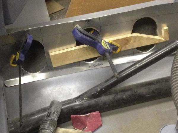
Christmas, 2018: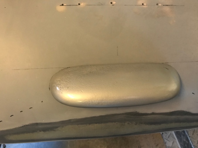
Present day:
OK, Spyderguy.....
Anything happening on the shop front or are you taking time off over the Holidays? (which I would not begrudge you one iota).
Re-fabbed my breather/fake oil tank out of steel 'cuz the aluminum one was too weak.


I'm also moving down my final assembly punch list: cleaned up under the dash today, riveted in the body tag, modded my throttle return spring so it's not ass. That sort of thing. There are about 115 individual punch-list items ranging from "top off transaxle with gear oil; tighten plugs" to "Visit MSP with docs for sign-off" to "install final Porsche scripts."
Attachments
Images (3)


Basic been that long?
Panicked a little when I couldn't get the backup light to work with the trans in reverse (knowing the switch was good); thought maybe I had a bum transaxle.

Then I tried pushing the car a little in gear. Low and behold: the fan spun counterclockwise in both reverse and second!
I was able to fix it pretty quickly after that discovery.
Also spoke to the safety inspector guy today and he's pretty sure—not 100 percent, but pretty sure—he'll have to see working windscreen wipers to give the car a pass. So I'll be saddling up the glass screen and delving back into my long-abandoned wiper rig before putting the floor back on the car.
All in the game, I guess.
Attachments
Images (1)
You're an inspiration to me, Ed. When life throws me the occasional wicked curve, and I whiff, I think of you and take another cut. Good on ya!
Yes that sucks about the windshield and wipers, I know another Maryland Spyder guy that swapped his screen out after the inspection.
Keep plugging away, Carlisle WILL BE MADE THIS YEAR. Unless it's sold before.......
edsnova posted:"...Low and behold: the fan spun counterclockwise in both reverse and second!..."
Ed, I think the technical term for that is a poltergeist .
I know you were focused on the switch and on whether or not it was working, but did you notice the demonic spirits escaping at the bottom of the photo?

Is your garage located anywhere near a cemetery, or maybe a former cemetery?
In any case, I'd stay away from your TV for a while.
Attachments
Images (1)
![]()
![]()
![]()
Yup....Those "Light Orab's" that haunt photographs on occasion can be downright frustrating...even scary. The one I have trouble with is the Gay little "Amp" that goes around blowing all the fuses randomly. They always catch you off-guard. So much so, that as soon as a fuse blows, you don't believe it happened so you install another fuse and watch to be sure it blows too. This is very common troubleshooting procedure and is why I always carry 2 of each size of fuse.
Sometimes I insert a screwdriver into a randomly selected device or assembly just to practice this unique skill and be reassured that the procedure still works.
Occasionally I practice it using an "ice-pick" style trouble shooting light. I make sure the shaft of the "pick" part is resting on a grounded part of the assembly. This is to "steady" the insertion of the "pick" enough to ensure it only touches the hot post !
Bruce
All this tiime I thought is was angels ![]()
Shift linkage/bracket adjustment continues apace!
Reverse gear is not reachable by standard means yet unless the works are adjusted such that it is the only gear that can be selected.
I pondered this phenom for a bit and finally decided that my home-brewed gate selector bracket is not yet ready for the big leagues, and set about adding a triangle to it for stiffening purposes.


I designed this as a bolt-on but, having tacked it together, I find I can't remove it without taking at least one of the two brackets off the trans, so I'll probably end up welding it to both brackets to make them into one big bracket like Brandwood made originally.
It's admittedly no longer elegant but it should not draw undue attention to itself under the spare tire.
For those needing a refresher here's my November, 2017 blog post on why I decided to make this mess instead of just using the stock bracket like a sane person.
Attachments
Images (5)


Hope springs eternal
Anything limiting motion (or allowing too much play) at the shifter end?
When we installed a Vintage shifter in my car, it turned out just the thickness of the carpet was enough to change the geometry and prevent proper shifts. Yeah, an entirely different system, but you get the idea, right?
Thanks for that, Mitch. I don't think the trouble's at the box but I do plan to double check and shim it up if necessary.
Spent four hours today. First I tried the shifter in reverse with the bracket/gusset just tacked in place. It worked! So I pulled the assembly and finished welding the shifter gusset.

I worked around it slowly so as to not warp it. Then I sliced the top of the tube and tapped it down to make it conform to the plate bit before welding across.

Then I was going to weld the new part to both the old parts to make it one unit but decided not to do that when I went to test-fit it on as a one-piece item and could not get it to fit under the holy frame bit I made.
The rearward part that attaches to the end of the bracket is threaded for the little ball that the cable end grabs. The upper part of course fits over the stud on the transaxle and is notched to kind of "lock" in place against one of the ribs. So I guess that'll have to be good enough.
Painted it.

Re-bent the reverse light bracket to tuck the light up, prepped and painted that too while I was at it. Also re-painted part of shifter bracket that got dinged-up from previous bending and bending back. I then reassembled all the bracketry and adjusted the shifter.


All four forward gears work easy now and reverse is where it should be.
There are 73 items remaining on the punch list.
Attachments
Images (5)
Just 103days until Carlisle you'll make it Ed !
I'll make it if I can avoid adding **** to the punch-out list.
72 items remain.
67 items left on the punch list.
I have 39 items to somehow get done by next Saturday AM when the guys come back to move the speedster body off the saw horses and onto the chassis.
Pulled the plastic windscreen off last night and riv-nutted the mounting holes for it and the glass screen.

There are a couple spots where the plexi screen holes almost coincide with the glass screen holes—so much so that I could not fit the thick-draw 6-32 rivet nuts that close together.

Fortunately, I made allowances for this, and bought a whole big pile of other 6-32 riv-nuts made to fit in thin aluminum. Turns out the barrles of these are way smaller. After grinding a little on the flanges and squeezing them ever so gently in the holes...

...I got them Siamesed in place so they should hold. They can't spin against each other!
Popped the Speedster windshield base on and thinking it should be a snap to make these interchangeable—except for the little problem of caulking the bottom of the glass rig to keep actual rain out. Maybe wax all surfaces generously first so the caulk will peel away easy at changeover time?

Moving right along. I plan to install the tonneau Tenax studs while all screens are absent. I'll probably install the dash grab handle as well since we're over here drillin'.
Attachments
Images (4)
Ed, Instead of the caulk issue, get yourself a thin rubber strip ( bike inner tube ) placing that between the cowl and windshield . OR you can use a piece of Beetle rubber fender welting that has a 1/8" bead ,
edsnova posted:
...except for the little problem of caulking the bottom of the glass rig to keep actual rain out....
I thought the whole reason you chose that color blue was that it matches pretty close with blue painter's tape for when it rains.
I used the VW fender welting on my second Speedster per Dr. Clock's recommendo and it worked (and looked) Marvelous!
I actually have some fender welting handy so we'll see what goes.
Seems OK. For a temporary deal.

Rechecked my toe-in on the rear wheels and it looks OK too.

After that I measured the distance from the front of the front tire to the back of the rear tire on both sides and tried to adjust it so it was the same. Sixteen measurements and 14 taps-and-tightens later, I thought I had it within a 16th, but no. On final measure, once again, I'm an eighth inch long on the passenger side. 

Given the precision of my alignment tools (a bed frame and tape measure), I'm calling it good enough to test drive.
68 items remain.
Attachments
Images (4)
Measure from center of grease cap to center of axle/castle nut. That will be more precise. And remember rear toe is measured off each wheel but also with respect to car center line, which is called thrust angle. After rear ride height(camber) and toe/thrust angle are set, then set front camber, then finally front toe.
You can align a Spyder with a tape measure and a carpenter's square.
And may I suggest less poems/song lyrics would result in more checks off the list? LOL!!!!
Clean under dashX
Pull seats, hook up heatersX
Test heatersX
Install seats with nylocks and washersX
63 items left now. 


Attachments
Images (3)
Ed... I'm sorry if I missed it but are you going to keep that color of blue on the body ?
Bruce
That's the color, Bruce.
And a spectacular color it is, Ed. 👍
Floors are back in.


There are 24 punch-list items remaining before I take the car to the MVA for inspection and titling; 54 items total.
Attachments
Images (3)
The driver's door is back on the car.


14 items to go before we visit the State Policeman and then the MVA.
Attachments
Images (3)
edsnova posted:The driver's door is back on the car.
14 items to go before we visit the State Policeman and then the MVA.
Just make sure it's not the other way around. We don't want you visiting the MVA then having you visited by the State Police. Ruh Roh.
Working on the rear belly pan.


Attachments
Images (4)


Still at it...


Attachments
Images (5)


Ed, some day you're going to look back at all of these build photos and take great pride in what healthy breakfasts you were eating.
Ed: This belly pan you're doing looks superb. Nice job! I am truly impressed by your fabrication skills and am enjoying your journey immensely.

Attachments
Images (1)
Beautiful job, Ed!
Impressive, Ed! ![]()
I'll do a full blog post when I'm done, along with an over-detailed explainer.
So far I have about 40 hours in it. Probably halfway done; lots of pieces still need to be CADded, bent up and fit and then probably re-bent and re-fit before they're drilled and attached with sheet metal screws...then taken apart and fixed with riv-nuts and 6-32 SS screws per final spec. before reassembly.
Oh...and more louvres too.
If I'd have foreseen the time this part would take I probably wouldn't have gone ahead with it. This is definitely a don't try this at home detail.

By the way: "Template main underpan" and "Cut and test fit main underpan" are just two items on the punch list. I'm marking one of them done.
Attachments
Images (1)
Hey Ed,
Super work as usual. Keep the pic’s coming. Also, if you keep your patterns for the under surface tins and how to’s a lot of us Spyder owners may be interested in buying a plan if you’re willing.
Pete
Beck/SE Spyder & Beck S/E Speedster
Super work as usual. Keep the pic’s coming. Also, if you keep your patterns for the under surface tins and how to’s a lot of us Spyder owners may be interested in buying a plan if you’re willing.
Pete
Beck/SE Spyder & Beck S/E Speedster
HOLY CARP! You made the louvers, too? I thought you inserted a pre-made vent panel!
Hot Rod Charlie has a machine for pressing out louvers and I've watched him use it (on steel and larger louvers than you made) - it is a very precise, very time consuming process, even with a machine that lines up on one or two axis. Yours look pretty good so my hat is, once again, off to your efforts and accuracy.
Wow!

Attachments
Images (1)
I did not make the louvres. They're folded in.
So has anyone incorporated a proper Bug thermostat and engine warm-up flaps into their Spyder build? Because I got an idea...
"Because I got an idea..."
Uh oh. Ed might not make Carlisle after all. ![]()
edsnova posted:So has anyone incorporated a proper Bug thermostat and engine warm-up flaps into their Spyder build? Because I got an idea...
Uh oh. That could take some time for sure. Carry on.
Keep them cards and letters coming, folks.
It's a serious question that arises naturally from the underpan effort. Since we're doing the full "hot-side-hot-cool-side-cool" treatment the question arises first of what to do about the oil cooler air (ducted out the back of the Raby DTM), which I've solved pretty much, and second what to do for warm-up since, if this all works as designed, I'll have a car that ducts virtually all the hot cylinder air and exhaust pipe heat down and out and behind the vehicle, leaving little or none to recirculate through the fan.
—all of which should be a very good thing ... once the cylinder heads get to 250 F and the oil temp reaches 180 or so.
But when might that happen??
So, yes. I'm pondering ideas and studying old Beetle thermostats and flaps.
No one here uses them, or anything like them, on anything?
I have an Awesome Powdercoat set-up for the bus 2110: 36 hp Scat/EMPI shroud, modified for a Type 4 oil cooler and OG German flaps, aforementioned flaps, Mexican thermostat, and EMPI sled tins modified for no heater boxes. The price of everything exceeded a new DTM.
Everybody raves, raves, raves about the flaps and thermostat. It works well enough, but the whole thing strikes me very similarly to the "don't even think about putting a fuel filter in the engine compartment" thing. I'm not sold that this doesn't fall into the "folklore and common knowledge" slot.
Ed,
As I wrote, keep the pic's coming. You've been doing a super job! I have followed quietly.
I have the same Raby DTM series motor as you in my Beck/SE Spyder. I stuck an 8" diameter e-fan under my spare tire and made a thin tin duct to blow air into the DTM fan I only use it when it's super hot out and I'm sitting in our wonderful traffic here in the DC area.
I haven't posted to the SOC in a while as I've been enjoying my 60 Austin Healey Bugeye with a Donald Healey hardtop since it has heat. It's a ton of fun in the winter though I've been out in the Spyder in 27 degrees, Just have to dress warm.
I keep thinking I need to make a pilgrimage up to see your Spyder build in person. I met you with Syl at Carlisle a year or so ago.
Pete


Attachments
Images (9)
Love that Bugeye!!! ![]()


Anyone know a source for flexible ducting that fits the oil cooler outlet? It's like 3 3/4 x 1 1/2 inches.
Attachments
Images (3)

Cory has a DTM. So does Lenny.
Ed: A piece of semi-rigid flexible aluminium clothes dryer outlet ducting.
Yes, I know it is round when you buy it, but it can be formed into a rectangle with a couple of boards like a press brake and one of the sizes should match what you need (and look cool, too).
Thanks, Gordon. The 3-inch is close but just a tad too small to fit over the outlet on the DTM. If all else fails I guess I'll make an adaptor.
Maybe a shop vac accessory (heavy black plastic ) modified suction end could cover the DTM outlet and then on the other end of it 2-3” diameter or so of flex pipe could be attached. I’ve sort of considered this myself for mine. Good luck.
Pete
I'd build a small duct with .060 Aluminum. Drier vent is going to dent if you look at it wrong. Standard sheetmetal will rust once the paint chips.
Yeah Stan, always aluminum; probably gonna do something like that. I'll mock it up in cardboard and see how complicated it has to be to integrate a flap. The design would appear to be akin to a very basic HVAC butterfly valve, but space is tight....
Attachments
Images (1)
Yeah, looking pretty awesome, Ed!

Ed, I wouldn't do a thermostatic flap where the oil cooler is. The factory thermostat blocked the flow of air to the heads and cylinders.
But ductwork, yes, good idea.
I get it, Danny, but why not? It's a way to pump (and pull*) modestly heated air into the place where the fan will suck it in. Probably not as good as stock but maybe better than doing nothing?
Cardboard tells me it could work as planned, mechanically speaking. Whether it would make any difference to the engine, good or bad, is another matter.


==
*my theory is the flap, pulled just beyond horizontal, will cause the fan air to Bernoulli the rising, exhaust tube-heated air up and into the engine bay as well, effectively (or not-very effectively?) transforming the 3-4 exhaust pipes into a cheap and cheesy heat exchanger.
Attachments
Images (4)
Ed, I like your reasoning and duct design. I also, like Danny, would err on the side of fewer chances of obstruction and go for simplicity in a minor subsystem. You are building an unbelievably great vehicle. Nice work!
Mike
edsnova posted:I get it, Danny, but why not? It's a way to pump (and pull*) modestly heated air into the place where the fan will suck it in. Probably not as good as stock but maybe better than doing nothing?
*my theory is the flap, pulled just beyond horizontal, will cause the fan air to Bernoulli the rising, exhaust tube-heated air up and into the engine bay as well, effectively (or not-very effectively?) transforming the 3-4 exhaust pipes into a cheap and cheesy heat exchanger.
I'm not seeing how the air would be even modestly heated when the engine is cold.
If the engine is cold enough for any of this to matter, it'll be cold enough for the oil to be bypassing the cooler. The cooler won't have hot oil circulating through it, so the air would be pretty much the same temperature coming out as it was going in.
As for the Bernoulli effect on the exhaust, I suppose that's possible, but I would also suppose the effect to be really, really minimal.
I'm wondering (in a Spyder, especially) why any of this matters. If you are operating the car, it's warm outside. If it's warm outside, and the engine is even modestly hopped up, it'll make more than enough heat eventually. If you are trying to prolong the life of an engine that will certainly see less than 4000 mi/yr of action, then you are worrying that the engine might need to be rebuilt in 2040 instead of 2045 (and that is being generous).
If you want to do it because you want to do it-- then I completely understand that.
Carry on.
Well, Stan, 30 seconds after startup those headers are waaay too hot to touch. Hot air wants to rise. But...
You guys are right: It's a bridge too far and at least a misdemeanor violation of the KISS principle. It's long past time I wrapped this project up. I'll just duct it down and out and let the N.O. worry about not having thermostatic control during warm-up.
Thanks for your kind and experience-inflected advice.
Ed.....I like that you introduced the Wheaties Box into your CAD !..........Bruce
I'm just wondering how big of a plastic container you have to hold all of the Wheaties that are not in your CAD system :-)
I eat a lot of cereal. Also, turns out, the duct work I've been playing around with is exactly the size of a Girl Scout Thin Mints box. So life is good.
And doubly fortuitous for you, since the Girl Scouts are currently out in force pushing their cookies!
Update. I buggered-up my knee last week so stayed out of the shop for a few days. Also, this is really hard. At this point I'm going to have to trash a few complicated folded parts I made and re-think some things before going at it again.
I'll get there though.


Attachments
Images (3)

Looks great! Hang in there!
Pete
Pete
Yep, my body behaves like I bought it at Harbor Freight. Hope your knee recovers quickly. Good luck on the new planning for the folded metal. Maybe you can reuse some of the pieces?
Transition pieces flare out to cover the fronts of the mufflers. Tricky to make, tricky to fit, and very tricky to make and fit in such a way that allows one to access the flange bolts holding the exhaust on. 
Attachments
Images (1)
Solved it. Stay tuned.
Slowly, ever so slowly, massaging it into shape...


Attachments
Images (3)
Riveting the pieces together. Getting the edges flat. Trimming the sheet aluminum.
I'll share with you all that someone whose knowledge and opinion I respect deeply has advised me that this underpan ain't gonna cut it. He says I should just tear it off and carry on, and I frankly think he may be right.
But I also feel like, since I'm this far into it, I might as well carry on to completion, just to see how good (or bad) it turns out, and even if I do end up crumpling it up for the recycling guys.
Here's the rearmost bit fit up under the car again. As you can see, I still have to make a little plate to connect the broad, flat area in the back to the piece in the middle, which also still needs the louvres to be finally fitted.

There are also "doors" on each side to allow for access to the upper outside exhaust flange bolts. It would probably be best to weld both top bolts in as studs, facing backward, to make R&R of the mufflers easy.
And there's a little gap up front where it slides over the pipe shroud. I'll CAD that piece this AM I think.
After those things there's some more riv-nuts to make all the pieces fast. And some insulation for the ceilings of the pipe and muffler shroud bits.
It's actually getting there.
Attachments
Images (1)
I looked at doing the underpan years ago, and decided it was way too monumental a task to undertake. Good luck, Ed.
Thanks, @DannyP, I think if I were half as savvy as you at assessing the amount of time jobs will take I'd never have gotten started on this. Last night after dinner I hammered out a piece to shroud the cutout for the gate shifter cable anchor.


I got back after it for two hours this am:


This piece will get rivets tonight or tomorrow. The trick to doing this, apparently, is you have to assemble it with all the fasteners before trying to shape or fasten anything else to it, or else everything that's not what your working on will change shape.
With this little bulb thing on it I made the (much simpler) close-off plate for the back and started on the last two bits of flat bar reinforcement.


Attachments
Images (10)
What a freak-load of work.
You sir, are the man.
"Oz never did give nothing to the Tin Man, that he didn't, didn't already have"
Minimal fiberglass seems to be what Ed is aiming for.....
Couldn't you just send the marked-up Cheerios boxes to China for the fabrication?
DannyP posted:"Oz never did give nothing to the Tin Man, that he didn't, didn't already have"
Minimal fiberglass seems to be what Ed is aiming for.....
Don't give him any more ideas...
Mike Danny is simply trying out his singing skills.
Louvres test-fitted.


Mufflers test fitted...


This is an enormous PIA, by the way. The mufflers would not slot in until I removed that stiffening plate I just made in the back. The shrouds kind of curve around the mufflers and so you have to leave the pan loose and jiggle the exhaust in.
Just a few more little pieces to make and then some final thread-certs and rivets, clean up, tapping, etc.
Attachments
Images (6)
The underside is looking really mean, Ed. Are you thinking about painting it? I kind of like the track-side look of the metal.
Super Ed! Tons of hard work paying off.
Pete
Pete
Good God, Ed! Incredible!
Not painting it.
I wouldn't paint it either. It's perfect as-is.
Great skills.
Totally incredible work and talent Ed !
Thanks all.
It's quite far from perfect and, as proud as I am of it, I'm still not sure it's going to make the final cut.
Sort of like a first draft of a very long, complex article. You write and write and, if you're in a good groove, you feel really good about it—and it IS really good!—but it still needs an editor.
And the editor might ask a question you can't answer, and that might be a fatal thing that causes the story to be killed, and you might even get mad but, in the end you'll be glad they asked that question and saved you from embarrassment or an even worse disaster.
In terms of my current skills, this piece is like a rough draft of the second long magazine article I ever wrote.
The good news is it can all be taken off the car in under an hour (putting it back on is closer to two) so it's an option either way.
And I am learning a lot.
I do hope you decide to keep it all, Ed.
I just can’t put out of my mind all of those Cheerios boxes that will have been needlessly sacrificed.
Bloody amazing what you have done here, Ed...
Loving this!! Go Ed!