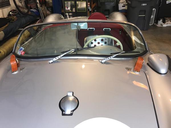
Welding...
Looks like you're not getting penetration ... i.e wire feed speed, heat, tip.
Looks like I rushed because it was dinner time. Luckily, a couple years ago I got a grinder for Christmas.
Nominally better this morning.

"Make the noise..."
Make the saddle snap on...


looking more passably like

Attachments
Turn the heat up. Everything is laying on top.
Attachments
I was gonna say it looks a little like not enough gas shrouding as well.
Nice fabrication Ed!
Yeah. Flux core gonna spatter. I've been judicious with the heat setting because I'm used to the 220 AC stick welder, which blows holes in anything thinner than Abrams tank armor plate. This thing ain't like that. Cranked it up to "D" and made everything cherry red and melty.
Luckily, I got a grinder for Christmas (and Bondo).
Here's where we're at now.
Looking good Ed. You are now a Hole eman. ![]()
Great job Ed! Did you happen to weigh the piece before and after the holes?![]()
When I was drilling the hardened gears for my trans I had to buy carbide drill bits (HSS and even cobalt would barely make a mark), which when you break a bit (2-1/8" at $22 each and 1- 1/4" at over $50) in the middle of a set up it got pretty frustrating. I can't say enough about rotary tables, though- pretty neat equipment!
I've not weighed the stuff but I'm pretty good at estimating weight, and I estimate the big tubular piece (including the through bolts) is about 6-7 pounds. I'll look around for a fish scale to weigh it. The modified cross brace is about 6-7 ounces heavier than stock, and that saddle is a few ounces. The "Swiss Cheese" inner bracing is ridiculously light. Maybe 2 pounds, 3 tops.
I estimate the whole aluminizing-and-details project will total under 50. Maybe under 40. Running Vintage 190s instead of steelies should more than make up for the extra weight.
btw your car is awesome. I might copy the drilled wiper arms. Love the hard tonneau.
I love seeing what other people are doing because I love the details, sometimes it makes me laugh at myself. For example, I built a big 3/16" thick steel structure with welded cross members to support my front bumper, it probably weighs 25lbs. then I built a steel tube frame that hung off of it to support the battery, it probably weighs 3 or 4 lbs, total 29 lbs. Then I built a 16 ga sheet metal tray for the battery, probably 1 lb. then I punched and drilled a bunch of lightening holes in the sheet metal tray, probably saved 5 grams! BUT!... it looked cool! I think I'll add a second battery and drill out my wiper blades!
Ah, Chris, a few more pounds up around the front bumper of a Speedster will do it no harm, and might do it some good. It's out around that rear bumper that you want to be judicious with the 3/16-inch plate.


vs:


Moving on. Rear axles, spacers, calipers, etc. I've got to get this car rolling so my neighbor can use the lift this weekend.
Attachments
Attachments
Nice touch!
I can’t wait to see this car in the flesh, Ed.
Front frame extensions: shimmed up, through-bolted and welded in.
 Front jack points: welded
 Rear jack points: drilled, tapped, bolted-in and then welded


Front jack point pockets: bolted-up (temporarily, pending cleanup of the horn pockets).

Attachments
Looking good Ed.
Gonna do something like you did re towing loops. You've got two bolts into the frame and your loops are (I think) about where my bolt through the frame extensions are. I think you said ground clearance on that was about 4 1/2 inches? How's it working?
I ask because my idea is to use my bolts as the rear support and the jack points as the front, with the towing loops just in front of them, maybe 2-3 inches higher off the ground (and easier to reach) than what you did.
But before I get started I want to learn all I can about flat-towing Spyders with homemade towing rigs. And you're the only guy I know so far that's done it!
I have about 3.25" between the ground and the bottom of my tow poinst. I have bottomed out on them twice with a passenger. I do live in the mountains and the roads around here aren't exactly smooth or even. I'm OK with that.
I have yet to fabricate my tow bar. If I didn't have any plans for a tow bar, I would've made the tow/tie downs flat and had them stick out farther. I do use them as jack points though.
I did fabricate a spoiler that mounts to them, but I plowed my gravel driveway a couple of times with it, so I took it off. If I lived somewhere where I frequented highways, It might come into play, but it doesn't do any good on the twisty back roads that I drive on. I avoid 4 lane roads as much as I can.
Attachments
Cool, man. Thanks for the reply.
I'll get after the towing stuff at some point after the car is painted and the engine is in. I came up with a design I think will work with one of those universal 5k lb tow bars. It won't be discrete enough to leave permanently attached tho.
Made the air intake for the oil cooler. Still working out the shutter mechanism; may omit since the car is getting a Mocal sandwich thermostat...


etc...
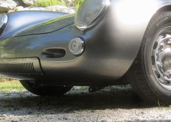
Obviously not exactly "as original" but I do get an extra cubic foot or so of frunk out of it, and I'm confident the oil cooler will get plenny enough air.
Attachments
That's pretty dang cool, Ed! ![]() @edsnova
@edsnova
Blog post catching up to the stuff I posted here.
I'm into the aluminum panels now but I'll save that update for later this week or next.
And thanks for all the encouragement. It keeps me at it.
Looking great Ed!
Didn't get much garage time this week (back to journalism for a few days). But the inner frunk panels are about finished.

Attachments
You really need to write a story for Reincarnation magazine when you finish this. Nice!
Wow! Looks great Ed. Only thing is you're taking away some storage area up front. I carry tools, jack, convertible top, etc. in those spaces. I like the extra room ahead of each front wheel and think it's good to have the lbs up front to hold the front down some during high speed.
Keep up the great work, gotta get my butt up to see your build in progress in person though. Bill from Potomac MD is swapping out his transmission for one that can better handle his engine he just built for his 550.
I spent some time making a LeMans red beehive pit crew light for my car and installing LeMans French roundel stickers as in the period pictures of LeMans racing 550's. I didn't want to drill any holes in the car so like my rear deck mushroom marker light and right side marker light I used and LED with a watch battery and micro switch to turn on and off. I used a Heineken aluminum beer can top as the base the plastic beehive fit it perfect on top and I had a beer! This was then UHU glued to the can top, I cut a slot into the beehive for the micro switch and press fit it with CA glue, wired it up to a 3 volt watch battery it works great and looks the part. Most folks won't know what it was for. My understanding is at night when racing at LeMans it was used to signal the pit's they were coming in. No radio coms back in 1955. ![]()
The back except around the battery was filled with a two part epoxy with enough room for the double sided 3M tape to stick it on the car. This 3M tape works great and you can get it off with some lighter fluid if needed.
Attachments
I love that story! I might even copy it depending on how the rest of this build goes.
BTW those frunk side panels are fit with six screws each. They'll always be easy to take out and put it.
Still cutting up this s.o.b...
Question for other Spyder guys, particularly Beck owners: does your car have a steel square tube running inside the cockpit bulkhead (directly below the dash)? Those rivets in the picture attach the fg to that steel. I did not drill the smaller holes in the fg so as to avoid messing with that steel. Any knowledge and/or advice much appreciated.
Attachments
ED,
Yes, my SE/Beck does. You can see it carpet covered in one of the attached pic's. When I replaced my clutch cable and throttle cable and rubber fuel line this Summer to make it easy to do, I used a hole saw and cut an access hole in the top. Suggest you think about doing the same without it it's a challenge to attach a new clutch cable and throttle cable feed.
Mine also has a shallow U shaped steel channel from the fire wall to the dash area FG brace. It holds the fuel line, e-brake lines, one hard brake fluid line and steel clutch cable tube. You can see this channel and what's in it. The cable shifter tubes are routed I think about half way from the shifter exiting from the channel under each seat you can see those too. This entire channel has easy acces you just have to remove the Velcro leather.
I changed the clutch cable through the std VW type access hole in my SE/Beck Speedster and it took a lot of contorting and time. I didn't want to ever have to do that in the Spyder or the Speedster again without better access. Having an access hole in the Spyder should make this job pretty easy to do on the road in an emergency (I carry a spare of each cable in each car). Pete
Pete
Attachments
Thanks, Pete. I figured it was standard-issue.
Just so we're clear though, I'm talking about what's under the latitudinal bit that's right in front of the shifter (as in your second pic, above). It's not covered by carpet; it's hidden by the rounded fiberglass bulkhead that you stick your legs over to reach the pedals. It ties the 3-inch round frame tubes together with that flat bit of steel that runs down the middle of the floor.
Mine has four small holes drilled through it to run cables, brake and clutch lines (you can just make them out in the pic). I had assumed that running those through would be relatively straightforward. I'd very much like to hear the details about why it is not.
My question is cosmetic: does anyone drill the typical "lightening holes" through the fiberglass part and if so, how to do it without compromising the brace, and how's it look afterwards?
My tendency here is to leave it as-is. I like the look of the holes, and the car I'm copying has them, but—despite all evidence—there are limits to my fanaticism in this regard.
Ed, my Vintage has a 1 x 2 rectangular beam there. It is structural. The car has two "lightening" holes on each side OUTSIDE of the main frame rails.
I wouldn't cut any more holes in that crossmember than I had to.
Attachments
I found some wheels for ya. No tire balancing needed - just drill another hole. Side benefit is they whistle to alert deer that might jump in front of you. These have been approved by "Swiss Cheeze" ALB-

That looks well-engineered, doesn't it?
Heading back out to the garage. This alloy stuff is remarkably slow-going, fwiw. Much, much fettling.
And to think: this is all going to be under vinyl anyway...


