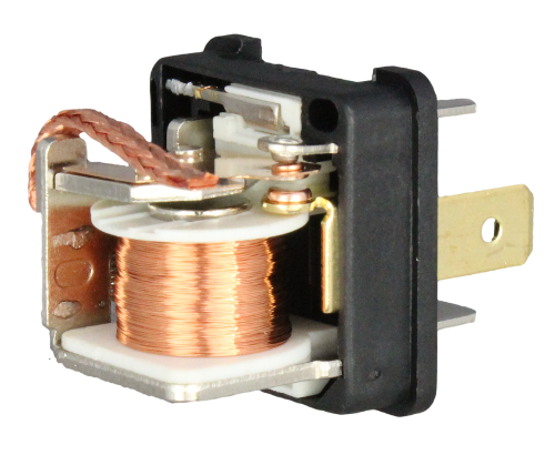
I recently got a PM from a member who was wondering this very question.   He understood that everyone was saying that it was a good thing to do, but couldn't understand WHY it was a good thing.  Specifically, he was wondering how relays are protecting the switches that power devices.

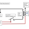
So here, for you folks who don't get into electrical things much, is Basic Relay Operation 101.  First, a drawing of a switch and a relay (and bear with me - the first time the photo didn't take so I attached a powerpoint file, too).  

The numbers correspond to terminals on the relay - they are usually numbered the same, especially if they are German.

Slide1

Power comes from the battery through a fuse in the fuse panel or through an in-line fuse apart from the fuse panel.  That's shown in red on the bottom.  A wire is then run from a fuse to a switch, let's say the headlight switch, and from the other side of the switch it is run to the COIL of the relay.  The coil is simply an electro magnet that closes a pair of contacts when 12 volt power is supplied from the switch.  It gets that power from the headlight switch when the headlight switch is turned "on".  That's half of the circuit.

The other half of the circuit is inside of the relay housing and is a separate pair of switch contacts powering the headlights.  12 volt power is run from a fuse separately to those contacts, independent of the dash switch, and then from the relay out to the headlights.

Why do all this?  Because the headlights require a lot of power to work - like 15 - 20 amps or more for the pair of lights.  That's a lot of power to run through a switch and it could make the switch contacts heat up and possibly wear out and burn over time.  So to save the switch from burning up, you need some heavy-duty switch contacts to handle the power and those are what's inside of the relay.  Most automotive relays are rated for 30 amps or more out to the device under load (Headlights, Fog lights, Heated Cup Holder, etc).

Inside of the relay is the relay coil, which only requires 1/2 an amp (often less) to close the relay switch contacts, so the headlight dash switch would only have to work with 1/2 amp, not the full 15 - 20 amps of the headlights.  At that level it'll last for many years and wear out from mechanical use before it ever burns out from too much power going through it.

Long winded explanation, I know, isn't it?  (it sounded a lot shorter in my head).  

Just think of it as a way to control a heavy duty load (the headlights) remotely, by a light duty switch (the dash switch).  That's pretty much it.

Hope this helps someone else!  Gordon


Attachments

Images (1)
  • Slide1
Files (1)
Original Post

Replies sorted oldest to newest


"...Just think of it as a way to control a heavy duty load (the headlights) remotely, by a light duty switch (the dash switch)..."


Yup Gordon, that right there is the main point.

But there's another big deal about relays - they let you keep wire runs to the load as short as possible. If you're a little smart about just where you put that relay, you can save the headlight switch AND make your headlights way brighter, too.

The heavier the load, the more important it is keeping wire runs short. You can lose a lot of power in just a few extra feet of wire and the difference in headlight brightness is obvious.

Since the battery in our cars is so close to the lights, using a relay mounted near the battery  to connect the two makes a lot of sense. The long 'control' leads that go from the relay back to the headlight switch aren't in the circuit to the headlights, so don't affect the brightness.

Relays for the win.


Ray, the 5 pin is the same as Gordon's 4 pin, labeled the same, with one added pin. 

Terminal 30 flip-flops between two terminals, terminal 87 and 87a. This is what's known as a SPDT, or single pole double throw switch(but controlled by a coil, becoming a relay). Terminal 85-86 for the coil are exactly the same.

No power applied to 85-86, there is continuity between terminal 30 and 87.

Power applied to the coil? Continuity between terminal 30 and 87a.

There can never be current flowing or continuity between 87 and 87a, unless somebody puts way more than 30 amps through the relay and melts it down!

I found this... 


https://www.12voltplanet.co.uk/relay-guide.html


Relay Guide
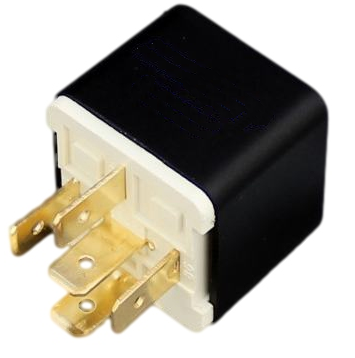
Automotive_relay.png

Overview

What is a relay?

A relay is essentially a switch that is operated electrically rather than mechanically. Although there are various relay designs, the ones most commonly found in low voltage auto and marine applications are electro-mechanical relays that work by activating an electromagnet to pull a set of contacts to make or break a circuit. These are used extensively throughout vehicle electrical systems.

Why might I want to use a relay?

There are several reasons why you might want or need to use a relay:

  • Switching a high current circuit using a lower current circuit

This is the most common reason and useful where an in-line switch or the existing circuit does not have the capacity to handle the current required. For example, if you wanted to fit some high power work lights that come on with the headlights but there is a risk that they would exceed the capacity of the existing loom.

  • Cost saving

High current capacity wiring and switches cost more than lower current capacity versions, so by using relays the requirement for the more expensive components is minimised. 

  • Activating more than one circuit from a single input

You can use a single input from one part of an electrical system (e.g. central locking output, manual switch etc.) to activate one or more relays that then complete one or more other circuits and so carry out multiple functions from one input signal.

  • Carrying out logic functions

Electromagnetic relays can be put to some quite clever (and complex) applications when linked up to perform logical operations based on certain inputs (for example, latching a +12V output on and off from a momentary input, flashing alternative left and right lights etc.). Although these logical functions have now been superseded by electronic modules for OEM designs, it can still be useful, fun and often more cost effective to use relays to perform them for some after-market projects (particularly where you have a bespoke application).

Note: In this article we are going to focus on ISO mini or 'standard' relays which have a 1" cube body and are the most commonly used in vehicle electrical systems.


Construction and operation

Inside a relay

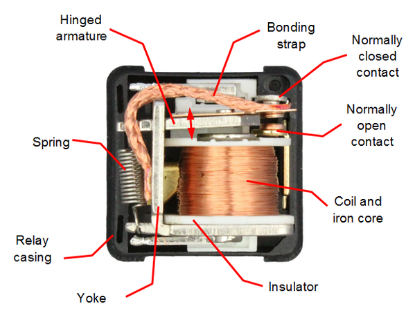
This is what the inside of an ISO mini relay looks like:
 Inside_of_automotive_relay.png      Make_and_break_relay_inside.png

A copper coil around an iron core (the electromagnet) is held in a frame or 'yoke' from which an armature is hinged. One end of the armature is connected to a tension spring which pulls the other end of the armature up. This is the relay in its de-energised state or 'at rest' with no voltage applied. The braided bonding strap provides a good electrical connection between the armature and yolk, rather than relying on contact between the armature pivot point alone. The coil and contact (or contacts) are then connected to various terminals on the outside of the relay body.

How they work

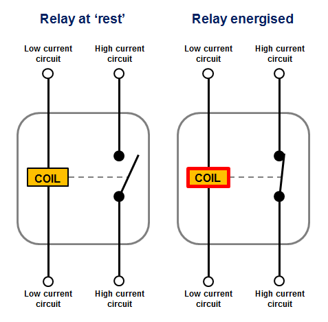
When the coil is supplied with voltage a magnetic field is generated around it which pulls the hinged armature down onto the contact. This completes the 'high' current circuit between the terminals and the relay is said to be energised. When voltage is removed from the coil terminal the spring pulls the armature back into it's 'at rest' position and breaks the circuit between the terminals. So by applying or removing power to the coil (the low current circuit) we switch the high current circuit on or off.

Note: It is important to understand that the coil circuit and the current-carrying (or switched) circuit are electrically isolated from one another within the relay. The coil circuit simply switches the high current circuit on.

The following simplified circuit diagram is often used to easily understand how a relay operates:
Simplified_relay_diagram_Sl.png 


Relay terminology

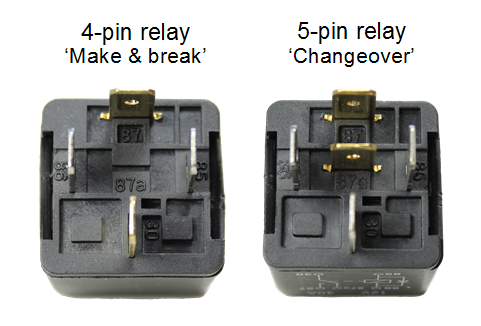
The ISO mini relay we have looked at above has 4 pins (or terminals) on the body and is referred to as a make & break relay because there is one high current circuit and a contact that is either open or closed depending upon whether the relay is at rest or energised. If the contact is broken with the relay at rest then the relay is referred to as Normally Open (NO) and if the contact is closed with the relay at rest then the relay is referred to as Normally Closed (NC). Normally Open relays are the more common type.

ISO mini relays with two circuits, one of which is closed when the relay is at rest and the other which is closed when the relay is energised, have 5 pins on the body and are referred to as changeover relays. These have two contacts connected to a common terminal.

Make & break relays are also known as Single Pole Single Throw (SPST) and changeover relays as Single Pole Double Throw (SPDT). This is based on standard switch terminology. There are other contact configurations discussed below but make & break and changeover relays are the most commonly used.

Terminal numbering convention

The terminal numberings found on a relay body are taken from DIN 72552 which is a German automotive industry standard that has been widely adopted and allocates a numeric code to various types of electrical terminals found in vehicles. The terminals on the outside of a 4 or 5 pin mini relay are marked with numbers as shown below:
 relay_pin_terminal_numbering.png

Terminal/Pin number

 Connection

 85

Coil

 86

Coil

 87

Normally Open (NO)

 87a

Normally Closed (NC) - not present on 4 pin relays

 30

Common connection to NO & NC terminals


According to DIN 72552 the coil should be fed with +12V to terminal 86 and grounded via terminal 85, however in practice it makes no difference which way around they are wired, unless you are using a relay with an integrated diode (see more info on diodes below).

Tip: you can use a changeover relay in place of a make & break relay by just leaving either the NO or NC terminal disconnected (depending on whether you want the circuit to be made or broken when you energise the relay).

Terminal layouts

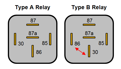
The automotive ISO mini relays we have been looking at above are typically available in two types of pin layout designated Type A and Type B layouts. These layouts are shown on the two 5-pin relays below (pin 87a not present on 4 pin relays):
Type_A_and_type_B_relays.png

You will notice that on the Type B layout pins 86 and 30 are swapped over compared with the Type A layout. The Type B layout is arguably easier to work with as the connected terminals are in-line, making the wiring easier to visualise. If you need to replace a relay make sure you use one with the same terminal layout as it is easy to overlook if you're not aware of the difference.

Terminal sizes

The terminal widths used on 4 and 5 pin relays are almost always 6.3mm wide, however some more specialist relays can have terminal widths of 2.8mm, 4.8mm and 9.5mm. The 9.5mm wide terminals tend to be used for higher power applications (such as for starter motor solenoid activation) and the smaller terminals tend to be used for electronics signalling where only very low currents are required.  All widths will be compatible with the standard female blade crimp terminals of the corresponding sizes.


Relay body markings

Relays can look very similar from the outside so they normally have the circuit schematic, voltage rating, current rating and terminal numbers marked on the body to identify them.

  • Circuit schematic

This shows the basic internal circuits (including any diodes, resistors etc.) and terminal layout to assist wiring.

  • Voltage rating

The operating voltage of the coil and high current circuits. Typically 12V for passenger vehicles and small craft but also available in 6V for older vehicles and 24V for commercial applications (both auto and marine).

  • Current rating

This is the current carrying capacity of the high current circuit(s) and is normally between 25A and 40A, however it is sometimes shown as a dual rating on changeover relays e.g. 30/40A. In the case of dual ratings the normally closed circuit is the lower of the two, so 30A/40A, NC/NO for the example given.  The current draw of the coil is not normally shown but is typically 150-200 mA with a corresponding coil resistance of around 80-60 W.

Tip: Knowing the coil resistance is useful when testing the relay for a fault with a multi-meter. A very high resistance or open circuit reading can indicate a damaged coil.

  • Terminal numbering

The numbers 85, 86, 30, 87 & 87a (or other numbers for different relay configurations) are normally moulded into the plastic next to each pin and also shown on the circuit schematic.


Attachments

Images (6)
  • blobid5
  • blobid3
  • blobid0
  • blobid1
  • blobid4
  • blobid2

OK... that's enormously complicated for something pretty easy.

A "Double-Pole, Single-Throw" (DPST) relay has a "common" and two switches, one of which is always made. The "Normally Open" (NO) switch is made (closes) from common to the NO contact when coil voltage is applied. The "Normally Closed" (NC) switch is made (closes) from common to the NC contact when voltage is taken away from the coil.

It's either/or, not both/and. They can't both be made or open at the same time.

Power is always looking for a ground. A stitch in time saves nine. A bird in the hand beats two in the bush. He who hesitates is lost. A penny saved is a penny earned. No good deed goes unpunished. Don't poop or pee your pants.

Forewarned is forearmed.

Last edited by Stan Galat

Whew!  After that in-depth treatise from Ray on the care and feeding of relays, I don't want to hear any more grumping about my posts being long.  Good thing he cut-and-pasted it.   

Back in the "Old Days" (before transistors and integrated circuits) there was a fair amount of "Relay Logic" being designed - circuits that depended on relays and primitive sensors to make "decisions".  But the coolest ones I ever worked with were telephone switching systems for rotary dial telephones (I'll bet Danny has seen a bunch of these, too, hopefully in museums).

Mechanical Telephone switching (stepper) relays were pretty cool buggers.....  They had 10 horizontal wafer switches stacked up 10 layers high in a vertical column, and at their center was a rod that handled the wiper (the arm that makes the relay connection in those diagrams up above).  The rod could be elevated in steps to a particular wafer switch and then rotated in steps to a precise position on that switch.  Remember, rotary dial phone, here, and also remember that the rotary dial itself was nothing more than a switch that closed (with a short pulse) for every number you chose: dial 3 and get three pulses, then a space while you dial the the next number for those pulses and so on.

 The first digit you dial makes the first stepper go up as many levels as you dialed ( 0 - 9 ) to that wafer switch.  The next number you dial makes the stepper rotate around that wafer switch to the dialed position (0 - 9).  The next number dialed goes to the  next stepper and makes it go up like the first to whatever number you dialed and so forth.  You needed 15 stepper relays in the system to allow for international direct dialing (all determined by the country code and then the number).  This system took, as input, whatever number you dialed on your pre-touch-tone phone and converted it from an analog (pulse) input to a pseudo-digital representation that the switching system could route to get you to the number you dialed.  All the system did was switch your "line" to another line determined by what series of numbers you entered.  

Pretty cool, huh?

Here's a very cool (and very old) video I found that 'splains it with pictures, so come with me, now, to those thrilling days of yesteryear when everyone had Bakelight, Rotary Dial telephones (and let's thank the crew at the Bell Labs for dreaming this system up):

Last edited by Gordon Nichols

"Whew!  After that in-depth treatise from Ray on the care and feeding of relays, I don't want to hear any more grumping about my posts being long.  Good thing he cut-and-pasted it.   "

Gordon, I was not trying to bombard the topic but I did find that sometimes when you have less experience having some documentation, that is well explained helps to have in your files.  My Thanks go out to you and others for the help you are on the list.    

Stan Galat posted:

OK... that's enormously complicated for something pretty easy.

A "Double-Pole, Single-Throw" (DPST) relay has a "common" and two switches, one of which is always made. The "Normally Open" (NO) switch is made (closes) from common to the NO contact when coil voltage is applied. The "Normally Closed" (NC) switch is made (closes) from common to the NC contact when voltage is taken away from the coil.

It's either/or, not both/and. They can't both be made or open at the same time.

It just proves that everything you read on the internet isn't true!

Practical example Why a relay...

Had an early Austin Healey 3000 Mk1;  there were NO relays in any circuit.  As bought by me, the dipper switch was failed and had melted the wiring to both headlamps to each other and the rest of the harness out front.  You may ask "what about the fuses?" There are two for the entire electrical system a 30 and a 50 amp (big and bigger) and they did not protect the wiring that had evidently melted before a fuse blew. 

I rewired with relays for lights and horn added to the replacement harness.


Veterans of this forum are more than familiar with the 'imported' replica switchgear that came standard on many of our cars and with how subject that stuff is to meltdowns. (There have been many threads here about all the smoky details.)

Which is to say, adding relays to these cars isn't being overly cautious at all.

The original switch in my car went toasty early on, but I didn't want to hassle finding a better switch with a bezel that would match the old one. So I got a new switch, identical to the first, but wired in a relay.

Six years and 30,000 miles later, I've still got lights, and the wiring has given up smoking.


Last edited by Sacto Mitch
Sacto Mitch posted:


I also found you don't have to be too particular about which grade of wiring harness smoke you use.

I just get whatever's on sale.


Stan Galat posted:
Sacto Mitch posted:

 I also found you don't have to be too particular about which grade of wiring harness smoke you use.

I just get whatever's on sale.

That won't work. The AutoZone smoke doesn't have any zinc in it.

Have either of you tried synthetic smoke? Is it as good as natural smoke?

Post Content
×
×
×
×
Link copied to your clipboard.
×
×